
FDN337N – Datasheet, Fairchild, Alternative & Model onsemi
- FET Type: N-Channel
- Drainto Source Voltage(Vdss): 30 V
- Current-Continuous Drain(Id)@25°C: 2.2A (Ta)
- Package: SOT-23-3


FREE delivery for orders over HK$250.00

Quick response, quick quotaton

Flash shipment,no worries after sales

Original channel,guarantee of the authentic products
FDN337N-NL-VB an N-channel SOT23 package MOS tube
FDN337N
The FDN337N from ON Semiconductor is a compact, low-power N-channel MOSFET ideal for efficient switching and power management. It’s designed specifically for small, battery-powered gadgets or devices needing fast, reliable switching at low voltages.
With a maximum voltage rating of 30V and continuous current up to 2.2A, this transistor can handle typical portable-device requirements easily. Its low on-resistance of about 65mΩ means minimal power loss and excellent efficiency.
Thanks to a low gate threshold voltage (1.2 to 2.5V), controlling it directly with microcontrollers or logic circuits running at 3.3V or 5V is simple, no extra parts needed. The tiny SOT-23 package fits perfectly where board space is limited.
You’ll find the FDN337N useful in applications like phones, wearable devices, LED drivers, small motors, DC load switches, and anything powered by batteries that needs high efficiency and quick switching.
FDN337N Pinout Diagram
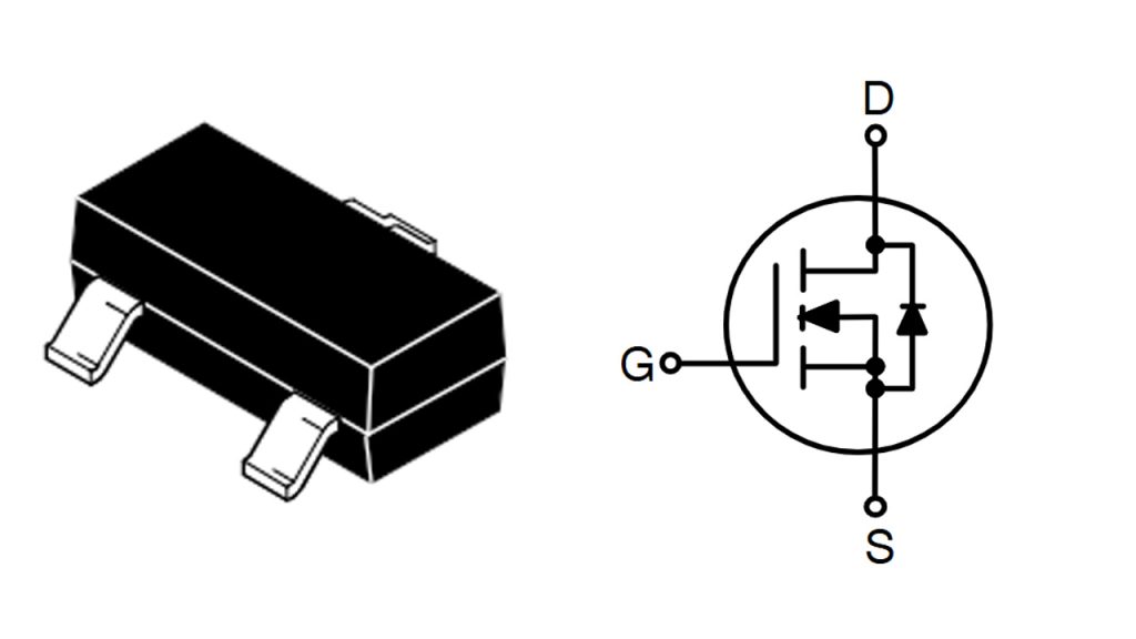
| Pin Number | Pin Name | Description |
|---|---|---|
| 1 | Gate (G) | Input terminal controlling MOSFET switching state, connected to control signals |
| 2 | Source (S) | Terminal where current flows out, typically connected to ground or reference potential |
| 3 | Drain (D) | Terminal where current flows in, connected to load or power supply |
When wiring the FDN337N MOSFET, keep the gate voltage below ±20V to protect the device. Adding a small resistor (10-100Ω) at the gate helps prevent unwanted oscillations. The source typically connects to ground as the reference point, and the drain connects directly to your load, with the other load terminal going to the positive supply—just make sure the voltage and current stay within 30V and 2.2A limits. MOSFETs are sensitive to static electricity, so proper anti-static measures help keep them safe. For continuous high-current operation, good heat management is essential to avoid overheating issues.
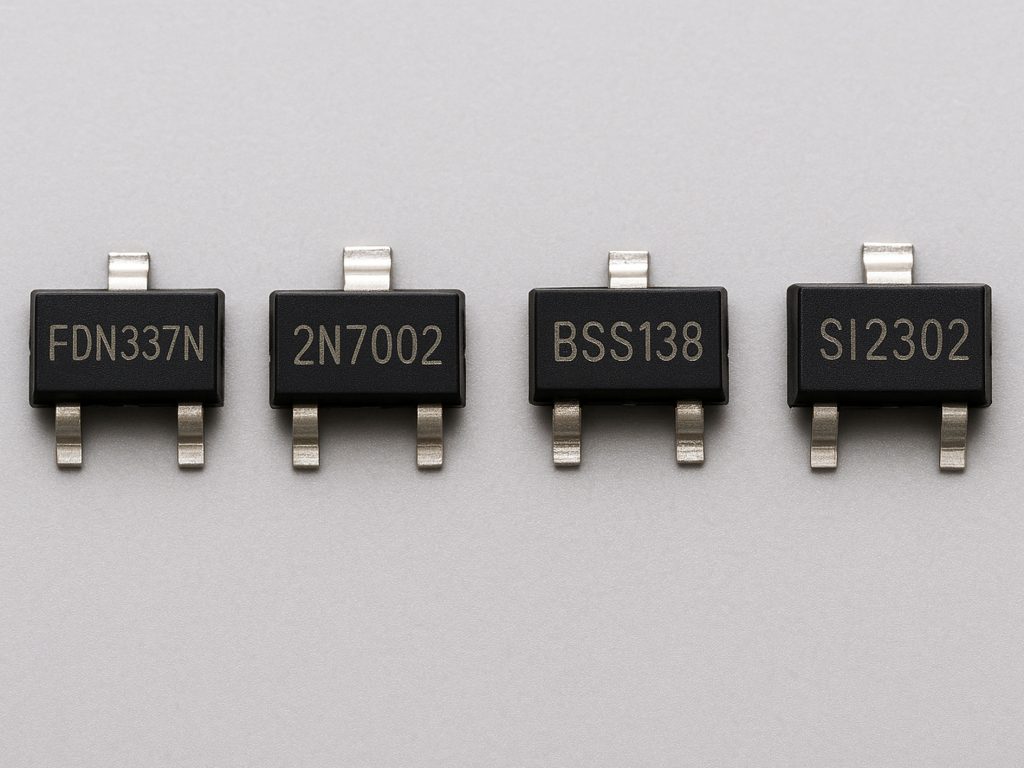
FDN337N Equivalent MOSFET Transistor
| Parameter | FDN337N | 2N7002 | BSS138 | SI2302 |
|---|---|---|---|---|
| Manufacturer | ON Semiconductor | Multiple Manufacturers (e.g., Diotec) | ON Semiconductor | Multiple Manufacturers (e.g., Chanzon) |
| Package | SOT-23 | SOT-23 | SOT-23 | SOT-23 |
| Max Drain-Source Voltage (VDS) | 30 V | 60 V | 50 V | 30 V |
| Max Drain Current (ID) | 2.2 A | 0.28 A | 0.22 A | 2.3 A |
| RDS(on) | 65 mΩ @ VGS=4.5 V | 1.2 Ω @ VGS=10 V | 3.5 Ω @ VGS=10 V | 45 mΩ @ VGS=4.5 V |
| Gate Threshold Voltage (VGS(th)) | 1.0 V | 2.1 V | 1.3 V | 1.0 V |
| Max Power Dissipation (PD) | 500 mW | 300 mW | 360 mW | 1.25 W |
| Suitable Drive Levels | Logic Level (2.5 V / 4.5 V) | Logic Level (≥5 V) | Logic Level (≥5 V) | Logic Level (2.5 V / 4.5 V) |
| Typical Applications | Power Management, Load Switches, Portable Devices | Low-current Switches, LED Drivers, Signal Control | Low-current Switches, Low-speed Circuits, Signal Switching | Power Management, High-speed Switching, Load Drivers |
When choosing a MOSFET to replace FDN337N, think about your application needs. For higher currents (above 1A), FDN337N (2.2A) or SI2302 (2.3A) work better. SI2302 also has lower R_DS(on) (45mΩ) compared to FDN337N (65mΩ), making it more efficient for high-performance circuits. Watch the gate voltage—2N7002 and BSS138 typically need at least 5V, so they’re not ideal for 3.3V logic circuits. All these alternatives use the SOT-23 package, so swapping them directly onto your board is simple. Pick SI2302 for fast switching and high efficiency, or 2N7002 for smaller currents and low-power applications.
FDN337N Switching Circuit Example
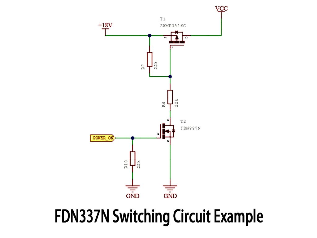
This circuit uses two MOSFETs to create a simple high-side power switch. A P-channel MOSFET (ZXMP3A16G) switches the main +18V power line, while an N-channel MOSFET (FDN337N) controls its gate.
When POWER_ON goes high, the FDN337N turns on, pulling the gate of ZXMP3A16G low and connecting +18V to the output. When POWER_ON is low, FDN337N switches off, and ZXMP3A16G’s gate rises, turning it off and disconnecting power.
The FDN337N makes switching fast and efficient. Keep resistor values (like R6, R7, R10) as shown for stable operation, and always check MOSFET ratings carefully, especially voltage limits and heat management.
FDN337N Load Switching Application
The FDN337N MOSFET is perfect as a load switch for low-voltage or battery-powered devices. It’s super easy to control directly from microcontrollers with 3.3V or 5V GPIO pins—no extra circuitry needed. Just feed a high-level signal to the gate, and it connects the load to ground, turning your device on. A low-level signal switches it off, cutting power.
With low on-resistance, it keeps power loss minimal and efficiency high. Fast switching means less wasted energy, especially useful for IoT devices, LEDs, relays, fans, and battery-powered equipment. Just keep within its voltage (30V) and current limits (2.2A), and consider diode protection for inductive loads.
FDN337N Gate Threshold Voltage
The gate threshold voltage (V_GS(th)) is the point where the FDN337N MOSFET just starts to turn on. Above about 2.5V, it fully switches on, giving the lowest resistance and best efficiency. If driving it directly with a microcontroller (3.3V or 5V GPIO), it’ll work great. For best results, use at least 4.5V to guarantee a solid connection and avoid unnecessary heat or power loss. Keep gate voltage comfortably above the threshold, because operating close to or below this limit can lead to poor performance. Also, remember temperature affects this threshold—build in some margin for reliability.
FDN337N Logic Level MOSFET Circuit
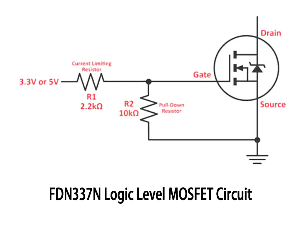
Here’s a simple MOSFET driver circuit you can use with logic-level MOSFETs like the FDN337N. Connect a 3.3V or 5V control signal directly to the MOSFET gate through a 2.2kΩ resistor (R1) to limit current spikes and protect your microcontroller pin. A 10kΩ resistor (R2) pulls the gate down, ensuring the MOSFET stays off without a control signal.
When the gate sees more than about 1.6V, the MOSFET switches on, powering your load—perfect for LEDs, relays, or fans. It’s straightforward, low-cost, reliable, and great for beginners or quick prototyping without additional components.
More Like This
~~3.jpg "IRFU9024NPBF")
IRFU9024NPBF
International Rectifier

FDG6335N
onsemi

MMBFJ201
onsemi

IRF3205PBF
International Rectifier

IRFP1405PBF
International Rectifier

IRF3205ZSTRLPBF
International Rectifier

IRFP4229PBF
International Rectifier

IRFB7437PBF
International Rectifier
.jpg "IRLR9343TRPBF")
IRLR9343TRPBF
International Rectifier
IRFP4468PBF
International Rectifier
IRF640NSTRLPBF
International Rectifier

FDS6375
National Semiconductor
Also Add to Cart

NVMFS4C01NT1G
onsemi

FCMT099N65S3
onsemi

CSD19538Q3A
Texas Instruments

SI4866DY-T1-E3
Vishay Siliconix

IRF740STRLPBF
Vishay Siliconix
.jpg "CSD17575Q3")
CSD17575Q3
Texas Instruments

IRFB4510PBF
International Rectifier

FDA28N50
onsemi
IRFU9024NPBF
International Rectifier

FDB031N08
onsemi
.jpg "IXTH52N65X")
IXTH52N65X
IXYS
;;2.jpg "STD5NM60T4")
STD5NM60T4
STMicroelectronics
Related Products
IRFU9024NPBF
International Rectifier
FDG6335N
onsemi
MMBFJ201
onsemi
IRF3205PBF
International Rectifier
IRFP1405PBF
International Rectifier
IRF3205ZSTRLPBF
International Rectifier
IRFP4229PBF
International Rectifier
IRFB7437PBF
International Rectifier
IRLR9343TRPBF
International Rectifier
IRFP4468PBF
International Rectifier
IRF640NSTRLPBF
International Rectifier
FDS6375
National Semiconductor
IRFB4332PBF
International Rectifier

IRFP3306PBF
International Rectifier

NVTFS5811NLTAG
onsemi
NVTFS4823NTWG
onsemi

NVD5117PLT4G
onsemi
IRF200S234
Infineon Technologies
.jpg "IRF840PBF")
IRF840PBF
Infineon Technologies

AO4407
Alpha & Omega Semiconductor Inc.

2SK3377-Z-E1-AZ
Renesas Electronics America Inc

NVD5867NLT4G
onsemi
NVMFS5A160PLZWFT1G
onsemi

FDWS9510L-F085
onsemi
FDWS9509L-F085
onsemi
NVTFS5826NLWFTAG
onsemi

AON7401L
Alpha & Omega Semiconductor Inc.
AO4407AL
Alpha & Omega Semiconductor Inc.

AO3407
Alpha & Omega Semiconductor Inc.

CPH3461-TL-W
onsemi
Please send RFQ , we will respond immediately.
