How to Read Capacitor Codes Like a Pro: Decoding the Markings
Author:admin Date: 2025-11-05 07:05 Views:407
Introduction
Capacitor codes are alphanumeric characters, color bands, or numbers that manufacturers use to label the key features of the capacitor on its body. The capacitor code provides vital information that anyone should know, including capacitance, voltage rating, tolerance, and capacitor type. Since capacitors are small in size, it makes it hard to print full details on them, and thus the choice of capacitor codes.
Importance of Capacitor Codes
Capacitor codes remain essential in electronics for safety, reliable circuit design, efficient manufacturing, and repair. These cryptic markings are essential in conveying the technical specifications in a compact form. Here are the reasons for capacitor codes in detail:
Circuit Design and Functionality
The codes ensure that the circuit designers can choose the right capacitor with the exact specifications. Using the wrong capacitance value in circuits or filters may lead to signal distortion or improper operation. Also, the codes can provide information on the tolerance and temperature coefficients, which are important for precision circuits where performance is key.
Safety and Reliability
Voltage rating and polarity identification with the capacitor color codes are important for safety and reliability. The codes help you understand the maximum voltage the capacitor can safely handle. If you use a capacitor with an insufficient voltage rating, then you risk it breaking down, overheating, bulging, or even exploding.
For polarized capacitors, markings help indicate the correct orientation. If the capacitor is not correctly connected, it can lead to immediate component failure.
Manufacturing and Repair
International standards such as those from IEC and EIA, they recommend the capacitor codes are the universal language for manufacturers and engineers worldwide. This ensures that components are interchangeable and readily available.
Also, technicians will have an easier time identifying and sourcing the correct replacement parts whenever a capacitor needs to be replaced.
Differences Between Modern and Legacy Capacitor Coding Systems
The primary difference between the legacy and modern capacitor coding system is that there has been a shift from using obsolete color codes to now using universal alphanumeric and numeric codes. The change was due to the need for more precision, standardization, and the ability to mark even the smaller components, such as the surface-mount devices.
Legacy Color Codes
In this case, older capacitors, such as paper, mica, or polyester film types, used a series of color bands or dots. The colors bands represented the first digit, second digit, a multiplier, tolerance, and sometimes a voltage rating.
The limitations of this system were that color misrepresentation was especially for those with colorblindness. Also, the colors could fade or be obscured by dirt.
The legacy color code is largely obsolete, and in its place is a modern naming system for color codes.
Modern Color Codes
The modern capacitor color code charts are designed to follow standardized systems. This includes Electronic Industries Alliance (EIA) and IEC standards. In this case, the manufacturers use printed letters and colors.
The advantage of this system is that it comes with better clarity, higher precision, and it is easier to read accurately. Still, you also get a wider range of color combinations depending on the specifications. It is generally more adaptable to modern automated manufacturing and assembly processes.
Understanding Capacitance Value Codes
The capacitor color codes come with different meanings. First, we look at the capacitance value codes and how you would interpret them. Take note that the capacitance is measured in picofarads (pF) in these codes.
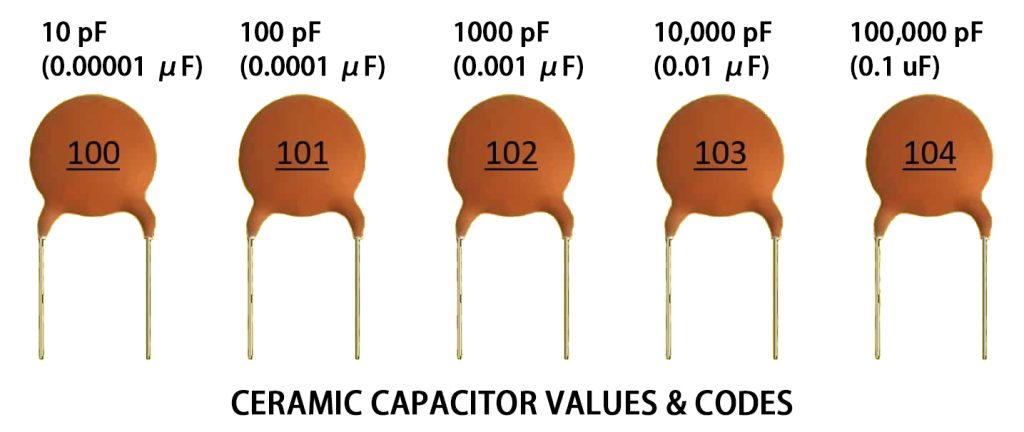
Standard 3-digit Code
This is an EIA standard and the most common system for small ceramic and film capacitors. The code has three digits. The first two digits indicate the capacitance value, while the third digit is a multiplier or the number of zeros to add after the first two digits.
The resulting value is always in picofarads (pF).
For example, for a capacitor code 473, the resulting capacitance is 47,000pF.
Alphanumeric and Decimal Codes
These codes are used for values less than 10 pF or non-integer values.
R is common example of a decimal point. It indicates the position of the decimal point for small capacitance values. For instance, 2R2 means 2.2F or R47 means 0.47pF.
You will also encounter unit designators such as p, n, and u. They replace the decimal point to indicate a specific unit. Examples include picofarad, microfarad, and nanofarad.
For example ,4n7 = 4.7 nF and 3u0 = 3.0 µF
Direct Marking
Larger capacitors, such as electrolytic and some film types, have enough space for manufacturers to print the value directly. A voltage rating often accompanies capacitance values. Eg. 2000µF 25V or 0.49µF 220V
Understanding Voltage Rating Codes
The voltage rating on the capacitor is vital to know the maximum continuous voltage the component will safely withstand without breaking down or causing damage. It is recommended not to exceed this rating as it can quickly lead to catastrophic failure.
The voltage information can be conveyed by using an explicit number or through standardized alphanumeric codes.
Direct Marking
This is common for large capacitors with enough space where the manufacturers can print the voltage rating in full on their bodies. For example, you can have 50V, 100VDC, and more.
If you want to use a capacitor in an AC circuit, look for one rated for VAC. Using DC capacitors in AC applications is not recommended.
Alphanumeric Codes
The smaller ceramic or film capacitors whose space is limited can use a two-character alphanumeric code developed by the EIA to indicate the voltage rating. The first character represents the voltage range, while the second character fine-tunes to the specific value in that range.
Here is an example table of how you can use alphanumeric codes for voltage rating
| Code | Voltage rating (VDC) |
| 0J | 6.3V |
| 1A | 10V |
| 1J | 63V |
| 2E | 250V |
| 2G | 400V |
Understanding Tolerance Value Codes
Capacitor tolerance codes are single letters that are printed on the component body. They indicate the permissible deviation and are expressed as a percentage of the state nominal capacitance value. This is vital for determining how the component is used in an application.
The tolerance codes follow the main capacitance value code. These codes are defined by the Electronic Industries Alliance (EIA).
| Letter Code | Tolerance (Percentage) |
| B | ±0.1 pF |
| C | ±0.25 pF |
| D | ±0.5 pF |
| F | ±1% |
| G | ±2% |
| H | ±3% |
| J | ±5% |
| K | ±10% |
| M | ±20% |
| Z | ±80% |
The letter is usually placed immediately after the three-digit capacitance code. For example, if a capacitor is marked 104K, then you interpret it as:
- 104: 100,000 pF
- K: There is a tolerance of ±10%
Temperature Coefficient and Stability Codes
You will also come across temperature codes as well. These codes specify how the capacitor’s capacitance value can change over a defined operating temperature range. This is critical for applications that need stable performance even in varying thermal conditions.
Class 1 dielectrics generally offer high stability and predictability. They are common in oscillators and filters. They have codes that define a linear temperature coefficient in parts per million per degree Celsius (ppm/°C).
The code has a three-character designation such as COG. But it can be more detailed, such as letter-number-letter. Here, the first letter indicates the temperature coefficient, the second number indicates the multiplier, and the third letter is the colerance in ppm/°C.
Class II capacitors offer higher capacitance as well in smaller packages, but have less stable properties in terms of temperature and voltage. They are commonly used in non-critical applications such as coupling and bypassing.
They also have a three-character code to define the operating temperature and the allowable maximum percentage of capacitance change within that range.
For example, X7R operates from -55°C to +125°C and comes with a maximum capacitance change within a range of ±15%.
Polarity and Orientation Markings
Polarity and orientation markings are also important for polarized capacitors. This includes electrolytic and tantalum types. They must be installed correctly in a DC circuit to prevent malfunction, explosion, or overheating.
There are several methods you can use to identify polarized capacitors, such as:
- Through Hole Components
New capacitors will have a longer terminal lead, which should be the positive terminal, and a shorter one, which will be the negative terminal.
Stripe/Band marking can also be used as an indicator. For example, you will see a prominent colored stripe or band running down on the side of the capacitor and often marked with multiple minus signs. This indicates the negative terminal.
- Surface Mount Devices (SMD)
SMD tantalum capacitors have a colored band or stripe indicating the positive terminal. Also, you may get some with a colored portion on the top or a strip along the side of the capacitor indicating the negative terminal.
Also, simply check the + or – signs on the body, as they help quickly identify the capacitor’s polarity.
Common Mistakes When Reading Capacitor Codes
It is possible to make mistakes when reading the capacitor codes. Below, we look at the mistakes and how to do it right.
Misinterpreting the multiplier
This is a common mistake with the three-digit code. This is when you misread the third digit as a value rather than it being a multiplier.
So, take note that the third digit is the number of zeros you have to add to the first two digits to give you the final value. For example, 104 means it is 100,000 pF and not 104pF.
Ignoring the base unit
By default, the base unit for a standard three-digit capacitor code is picofarads or pF. Using a different base unit leads to massive errors when designing a circuit. So, for the case of 104, it is 100,000 pF and not 100,000 nF or any other unit.
Confusing the polarity markings
It is always essential to install polarized capacitors correctly. These polarity markings differ between component types, which can be confusing. Always look for the + and – signs on the capacitor or a stripe indicating that it is a negative lead. There are capacitors with a longer positive terminal for ease of identification.
Underestimating the voltage rating
A capacitor has a voltage rating that you must always keep in mind. If you use a capacitor with a lower voltage than the circuit’s operating voltage, it becomes a significant safety hazard that may cause the capacitor to fail or explode.
Conclusion
Capacitor codes are important for understanding the specifications of capacitors. This includes learning about its capacitance, tolerance, voltage rating, and material, all presented to you in a compact format. So, mastering the interpretation of capacitor codes is an important skill for anyone working with electronics.
Please send RFQ , we will respond immediately.
Frequently Asked Questions
Why do most SMD ceramic capacitors lack printed codes?
This is because these capacitors are extremely small, making it hard to print legible text. So, their values will be printed on their packaging labels to make it easier to identify them.
How do you identify the polarity on electrolytic capacitors?
These capacitors are polarized and will come with a stripe marking indicating the negative terminal. Also, watch out for the positive (+) and negative (-) signs on the body of the capacity to help know the polarity.
Can you replace a capacitor with a different voltage rating?
Yes, using a higher voltage rating is generally safe so long as the capacitance value and the capacitor type match. You should never use a capacitor with a lower voltage than the circuit requires.