What Is a Circuit? Extensive Guide to How Electrical Circuits Work
Author:admin Date: 2025-11-05 06:33 Views:111
Introduction
It is possible you have come across a circuit, but you did not know what it meant. Well, a circuit is a closed, continuous path or loop through which an electric current can flow to power a device.
Expect to come across many types of circuits. It comes down to how it works, its components, and much more. We also look at the applications, how you can troubleshoot circuits, and much more. Let’s get into it to understand what is a circuit.
Components of a Circuit
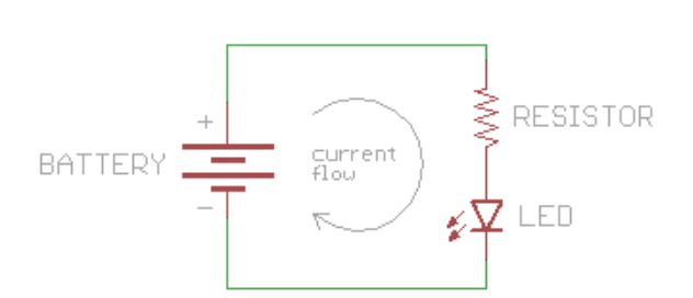
There are several components that are important to make a complete circuit. Here are the basic and essential components.
- Power source: This component provides the electrical energy needed to move the charge through a circuit. For example, a battery that is DC power or a household wall outlet, which offers AC power.
- Conductor: This is the material that forms the pathway for current to flow. The aim is to offer very little resistance to allow the electric current to pass through it with ease. Examples include copper and aluminum.
- Load: This is a device that consumes the electrical power in the circuit and converts it into another energy form. For example, light, motion, or heat.
- Switch: This is an optional component, but it is still important. It can open or close a circuit to intentionally start or stop the current flow to a device.
A circuit will also have passive components. These are components that do not generate power, but they can regulate or store it. The common passive components include:
- Resistors: These components reduce and control the amount of electrical current that flows through a circuit. They come in two main types: fixed resistors with a set value and variable resistors that can be adjusted.
- Capacitors: A capacitor holds electrical energy by creating an electric field between its plates. It’s commonly used to block DC signals while letting AC signals pass through, making it useful in many filtering applications.
- Inductors: An inductor is made from a coil of wire and stores energy in the form of a magnetic field. It resists sudden changes in current and is frequently used in filters, chokes, and tuning circuits.
We have already seen the passive components. How about the active ones? These are components used to control or amplify the flow of charge. Examples include:
- Diode: A diode is a component designed to let electric current pass through it in only one direction. It’s commonly used in rectifier circuits, where it converts alternating current (AC) to direct current (DC).
- Transistor: A transistor is a semiconductor device that can boost (amplify) signals or act as an electronic switch. In this case, a small current is applied to one of the terminals so that it can control a larger current between the other two terminals.
- Integrated circuits: This is also called a microchip. It is a miniaturized electronic circuit containing many components, such as resistors and transistors, on a single piece of silicon.
Common Circuit Applications in Everyday Devices
So, there are several devices we use daily that have circuits. Here is a quick list to show you that you have been exposed to circuits before.
- A refrigerator has circuits to regulate cooling and maintain a consistent temperature. You also get circuits for defrosting the freezer and powering the internal lights.
- A microwave oven uses complex circuits to generate microwaves for heating food inside it. It even has a series of switches that break the circuit if you open the microwave door.
- A laptop also includes a variety of circuits for power management, data processing, and more.
- An air conditioner has circuits to manage its core functions, including heating, air circulation, and cooling.
- The lighting system in the house or office is also a circuit. It can be configured in many ways to ensure optimal lighting conditions.
Open vs Closed Circuits
You will come across both open and closed circuits; however, what do they mean?
In an open circuit, there is a break in the path through which electricity normally flows. In this case, there will be no electric current as the path is incomplete. Also, the resistance is infinite or very high. The voltage potential still exists even with the break in the circuit. Since there is no current, the load in the circuit, such as a light bulb, will not work.
A good example of an open circuit is turning off the light by flipping the switch to the off position.
A closed circuit provides a continuous, unbroken path for current to flow freely and power a device. The current and resistance characteristics are the opposite of those of the open circuit. In this case, current is flowing through the circuit, and the components in it determine the resistance. So, the load in the circuit, such as a light bulb, will work as expected.
For example, when you flip the switch to the ON position, you now have a closed circuit.
Types of Electrical Circuits
Different types of circuits are used to serve different applications. So, it is important to always understand the types of electrical circuits to find the right one for you. Below are the common types and their applications.
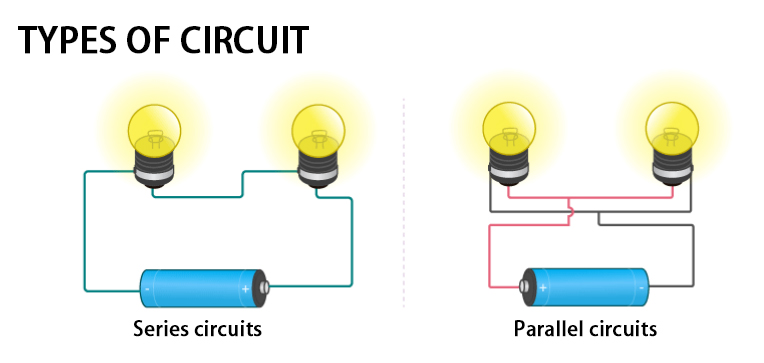
- Series circuits
In a series circuit, all components are linked one after another along a single continuous route. Because the electricity has only one path to follow, the current remains consistent throughout the entire circuit.
The total voltage from the power source is divided among the circuit’s components. So, when you sum up the individual voltage drops across the multiple components, you should get the total source voltage.
The challenge with a series circuit is that when a single component faults, then the entire circuit is broken. No current can now flow in the circuit.
To find the total resistance, simply add all the individual resistances.
Typical applications for such a circuit are flashlights, where multiple batteries are arranged in series to power them.
- Parallel circuits
In a parallel circuit, the parts are arranged on several separate paths, allowing the current to split and travel through each one. Every pathway operates on its own, unaffected by the others.
The current from the source is that one being divided in this case to flow into different branches. The current flowing in each branch depends on the resistance of the path.
As for voltage, it is the same across every parallel branch.
In case one component or brand fails, the other branches will still be powered. A good example is household wiring. It is designed this way so that even if one bulb fails, it does not cause a power outage in the entire room.
- Combination circuits
In combination circuits, there is a mixture of series and parallel circuits. It is common to have this type of circuit to optimize for different performance needs.
Some parts of the circuits are designed to operate according to series rules, while others follow parallel rules.
The internal workings of many electronic devices, such as computers and televisions, use combination circuits.
How to Get Power and Energy in a Circuit
The electrical power is the rate at which energy is converted or transferred. There is also electrical energy, which is the work done by a circuit over a period of time.
Understanding the relationship between power and energy in a circuit is important for learning about electrical efficiency and power loss.
Relationship between power and energy
Power (P): This is the instantaneous rate at which electrical energy is transferred or consumed. Power is measured in watts (W), which is also equivalent to one joule per second (J/s).
The formula for finding power is: P = V x I
Energy (E): This is the amount of work done by a circuit over a period of time. This is measured in joules (J). However, electricity providers will bill their customers in terms of kilowatt-hours (kWh).
The formula for energy is: E = P x t
Where
- E is the energy in joules (J)
- P is the power in watts (W)
- t is the time in seconds (s)
Efficiency and Power Loss
In any electrical system, some energy will be lost due to processes such as generation, transmission, and the use of electricity.
Efficiency is the ratio of useful output power to the total input power. The efficiency of a circuit is often expressed as a circuit.
A highly efficient device is supposed to convert most of its electrical energy to its intended purpose and waste less energy as heat. For example, a bulb needs to produce light while generating less heat.
The efficiency is calculated as (Output Power / Input Power) x 100%
Power loss is the energy dissipated or wasted mostly as heat rather than being converted into useful work. It is the difference between input and output power.
Power loss is an important consideration when designing systems, as it affects the operating costs and the system’s reliability.
How to Read Circuit Diagrams and Symbols
It is important to know the circuit diagrams and symbols to understand how the circuit works. Here is how to interpret a circuit diagram:
- Identify the diagram type. Using a schematic diagram shows the logical connections and the circuit’s function.
- Learn common symbols. Each component in a circuit will have a standardized icon or symbol. Make sure you familiarize yourself with the most common symbols to make schematics easier to read.
- Recognize the connections so that you can follow the power flow.
How to Troubleshoot a Circuit
Troubleshooting a circuit requires a good approach to ensure that you can identify the issues and correct them. Here are the steps to follow:
- Consider safety first
Before you can start working on any circuit, take the key safety measures to prevent possible electric shock or fire. So, start by disconnecting the power, if possible, unplug the device from the power source.
Verify that the power is off by using a voltage tester or a multimeter to confirm there is none.
- Do a visual inspection
Many problems can be easily identified by looking at the circuit. Start by looking for obvious signs of damage, such as burnt or discolored wires. Also, check for loose connections.
Ensure that all the switches are in the correct position. Sometimes the switch may be off, which is why the bulb is not working.
If the fuse or breaker is not working, have it changed to complete the circuit.
- Use a multimeter
A multimeter is great for checking the continuity test of a circuit. Start by setting the multimeter in the continuity mode and test the circuit using the probes. Place one multimeter probe on one end of the suspected component or wire, while the other on the opposite end. When there is a beep or near-zero resistance, it shows there is continuity. No beep or OL message suggests a broken wire.
You can also use the multimeter to test for resistance, voltage, and much more. It all depends on what you want to measure in a circuit.
Conclusion
A circuit is an important concept in electronics. It usually involves a lot of components to make the circuit work. So, the next time you design a circuit, ensure it includes the right components for the application. Still, you can experience issues with the circuit. Follow our guide to troubleshoot the circuit and ensure it functions properly.
Please send RFQ , we will respond immediately.
Frequently Asked Questions
Is there a difference between AC and DC circuits?
Direct Current or DC flows in one direction, and it is commonly supplied by batteries. As for Alternating Current (AC), it reverses direction periodically and powers many household devices.
What is resistance in an electrical circuit?
Resistance is the degree to which a material or circuit component impedes the flow of electrical current. It is measured in ohms and is often adjusted using devices like resistors. When resistance increases, the current that can pass through the circuit decreases.
What happens in the case of an overloaded circuit?
An overloaded circuit happens when more electrical demand is placed on a circuit than it’s designed to handle. When too many devices draw power simultaneously, excess current can cause overheating, tripped breakers, or even a fire hazard.