
ESP32-S2 pinout & bootloader, driver Windows 10, 11
- RF Family: WiFi
- Protocol: 802.11b/g/n
- Serial Interfaces: ADC, I²C, I²S, SPI, PWM, UART
- Package: Tape , Reel ,Cut Tape


FREE delivery for orders over HK$250.00

Quick response, quick quotaton

Flash shipment,no worries after sales

Original channel,guarantee of the authentic products
ESP32-S2-SAOLA-1M First Run
ESP32-S2
The ESP32-S2 is a powerful single-core Wi-Fi microcontroller that’s perfect for IoT projects. It comes with built-in Wi-Fi support on the 2.4 GHz band, making it ideal for wireless communication and remote sensing. Powered by a single-core Xtensa LX7 processor running up to 240 MHz, it offers enough performance for most low to moderate processing tasks. It’s designed to be power-efficient, with deep sleep modes that are great for battery-powered devices. Plus, it supports USB OTG, so you can connect USB devices like keyboards or storage directly. The ESP32-S2 also has lots of peripheral interfaces like SPI, I2C, UART, PWM, and ADC, and solid security features like Secure Boot and Flash Encryption. It’s compatible with ESP-IDF and Arduino IDE, making it easy for both beginners and pros to get started.
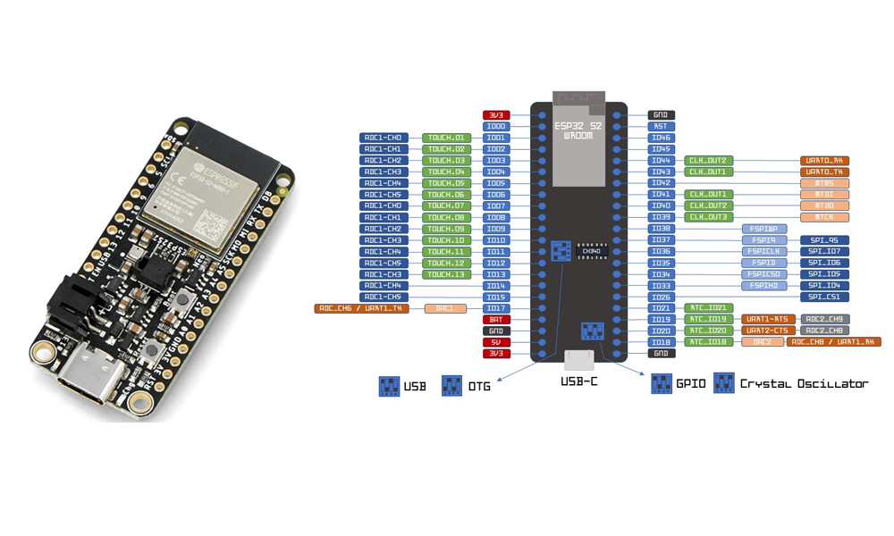
ESP32-S2 Pinout Diagram
| Pin Number | Pin Name | Function |
|---|---|---|
| 1 | GPIO1 | U0TXD (UART0 Transmit), General-purpose I/O |
| 2 | GPIO2 | U0RXD (UART0 Receive), General-purpose I/O |
| 3 | GPIO3 | U0RTS (UART0 Request to Send), General-purpose I/O |
| 4 | GPIO4 | U0CTS (UART0 Clear to Send), General-purpose I/O |
| 5 | GPIO5 | General-purpose I/O |
| 6 | GPIO6 | SDIO_CLK (SDIO Clock), General-purpose I/O |
| 7 | GPIO7 | SDIO_CMD (SDIO Command), General-purpose I/O |
| 8 | GPIO8 | SDIO_DATA0 (SDIO Data 0), General-purpose I/O |
| 9 | GPIO9 | SDIO_DATA1 (SDIO Data 1), General-purpose I/O |
| 10 | GPIO10 | SDIO_DATA2 (SDIO Data 2), General-purpose I/O |
| 11 | GPIO11 | SDIO_DATA3 (SDIO Data 3), General-purpose I/O |
| 12 | GPIO12 | SPI_CS (SPI Chip Select), General-purpose I/O |
| 13 | GPIO13 | SPI_CLK (SPI Clock), General-purpose I/O |
| 14 | GPIO14 | SPI_MISO (SPI Master In Slave Out), General-purpose I/O |
| 15 | GPIO15 | SPI_MOSI (SPI Master Out Slave In), General-purpose I/O |
| 16 | GPIO16 | General-purpose I/O |
| 17 | GPIO17 | General-purpose I/O |
| 18 | GPIO18 | I2C_SCL (I2C Clock), General-purpose I/O |
| 19 | GPIO19 | I2C_SDA (I2C Data), General-purpose I/O |
| 20 | GPIO20 | General-purpose I/O |
| 21 | GPIO21 | General-purpose I/O |
| 22 | GPIO22 | General-purpose I/O |
| 23 | GPIO23 | General-purpose I/O |
| 24 | GPIO24 | General-purpose I/O |
| 25 | GPIO25 | General-purpose I/O |
| 26 | GPIO26 | General-purpose I/O |
| 27 | GPIO27 | General-purpose I/O |
| 28 | GPIO28 | General-purpose I/O |
| 29 | GPIO29 | General-purpose I/O |
| 30 | GPIO30 | General-purpose I/O |
| 31 | GPIO31 | General-purpose I/O |
| 32 | GPIO32 | General-purpose I/O |
| 33 | GPIO33 | General-purpose I/O |
| 34 | GPIO34 | Input-only pin, for ADC input |
| 35 | GPIO35 | Input-only pin, for ADC input |
| 36 | GPIO36 | Input-only pin, for ADC input |
| 37 | GPIO37 | Input-only pin, for ADC input |
| 38 | GPIO38 | Input-only pin, for ADC input |
| 39 | GPIO39 | Input-only pin, for ADC input |
| 40 | GND | Ground |
| 41 | 3V3 | 3.3V Power Supply |
| 42 | EN | Enable pin, active low (reset pin) |
| 43 | IO0 | Boot mode selection, also used as GPIO |
| 44 | IO1 | Serial UART TX (for flashing) |
| 45 | IO2 | Serial UART RX (for flashing) |
| 46 | IO3 | GPIO, can also be used for Serial TX/RX |
When using the ESP32-S2, the GPIO pins are pretty versatile. You can set them up for general I/O tasks, and they can switch between functions like SPI, I2C, or PWM depending on what you need. But keep in mind that GPIO34 to GPIO39 are input-only, so they’re mainly for ADC tasks.
For power, you’ll want to hook up the 3V3 and GND pins correctly to avoid messing with your voltage levels.
And don’t forget about the EN pin! It’s what you’ll use to reset the chip. As for IO0, that’s the one you’ll use during the boot process to get into programming mode.
ESP32-S2 Equivalent WiFi Microcontroller

| Feature | ESP32-S2 | ESP32 | ESP8266 |
|---|---|---|---|
| Core | Xtensa LX7 single-core | Xtensa LX6 dual-core | Tensilica L106 single-core |
| Wi-Fi | 802.11 b/g/n (2.4GHz) | 802.11 b/g/n (2.4GHz) | 802.11 b/g/n (2.4GHz) |
| Bluetooth | No Bluetooth | Bluetooth 4.2/BLE | No Bluetooth |
| CPU Speed | Up to 240 MHz | Up to 240 MHz | Up to 160 MHz |
| RAM | 320 KB SRAM | 520 KB SRAM | 160 KB SRAM |
| Flash | 4MB (up to 16MB supported) | 4MB (up to 16MB supported) | 4MB |
| GPIO Pins | 43 | 34 | 17 |
| ADC Channels | 20 | 18 | 1 |
| PWM Channels | 16 | 16 | 16 |
| SPI/I2C/UART | Yes (Full Support) | Yes (Full Support) | Yes (Limited Support) |
| USB Support | Yes (USB OTG) | No | No |
| Package Type | QFN-48, WLCSP-32 | QFN-38, WLCSP-32 | QFN-32 |
When comparing the ESP32-S2 with the ESP32, the ESP32 has a dual-core processor and Bluetooth, making it more powerful, but it also consumes more power. On the other hand, the ESP32-S2 has a single-core processor and no Bluetooth, but it does have USB OTG support, which makes it great for projects that need USB connectivity.
As for the ESP8266, it’s a cheaper option with fewer GPIO pins and less RAM. It works fine for simpler projects where you don’t need too much processing power or Bluetooth. If you need more performance and extra features like more GPIO pins and USB support, then the ESP32-S2 is a better choice.
ESP32-S2 Dev Board Circuit Example

In the circuit, the ESP32-S2 board is the heart of the setup, connecting to a variety of components. The LEDs are wired to D15 and D2 pins, with current-limiting resistors (R2, R3) in place to protect them. These LEDs could be used for status indicators or other outputs. You also have two buttons, one connected to the EN pin for reset and another connected to D13 for custom functionality. For communication, the ESP32-S2 uses I2C and SPI protocols, with pins like MOSI, MISO, SCL, SDA, and CLK linked to other devices. The power supply comes from 5V, with a 3.3V output for lower voltage components. Don’t forget the GND pins—they’re essential for completing the circuit.
ESP32-S2 USB OTG Wiring Guide
When setting up USB OTG on the ESP32-S2, start by wiring it properly. You’ll need to connect the 5V pin to the power supply providing 5V, and don’t forget to link the GND pin to ground. For USB data, connect the D+ and D- pins on the ESP32-S2 to the same pins on your USB device.
In your firmware, enable USB OTG functionality. The ESP32-S2 can switch between being a host or a device, so make sure your software is ready for that. If you’re using it as a host, you can connect it to devices like keyboards or flash drives, and if it’s a device, it’ll act like a USB peripheral (like a virtual COM port).
Add capacitors or resistors if needed to improve USB power or signal quality. After everything’s connected and configured, test the setup. If it’s in device mode, plug it into a PC and check if it’s recognized. In host mode, connect a peripheral and see if it communicates properly.
ESP32-S2 Application
The ESP32-S2 is super flexible and can be used in a bunch of different projects. If you’re working on IoT (like smart home devices or weather stations), it’s perfect because of its Wi-Fi connectivity. You can easily link it to cloud platforms to monitor or control your devices.
With USB OTG, you can use the ESP32-S2 as a USB device—whether it’s a USB-to-serial adapter, keyboard, mouse, or even a storage device. It’s also great for wearables, especially if you need something with low power for fitness trackers or smartwatches.
If you’re into prototyping, this microcontroller is a solid choice. It works well with sensors, so it’s great for robotics or automation projects. And if you’re into audio or voice apps, the ESP32-S2 can stream audio over Wi-Fi or even be used in voice-powered devices.
More Like This

TDA5225HTXUMA1
Infineon Technologies

GNSSLC29D10
5G HUB

NCK2910AHN/00200Y
NXP USA Inc.
TEA6856HN/V102Y
NXP USA Inc.
TEA6856HN/V102K
NXP USA Inc.
TEA6856AHN/V205Y
NXP USA Inc.
TEA6856AHN/V205K
NXP USA Inc.
TEA6853AHN/V205Y
NXP USA Inc.
TEA6853AHN/V205K
NXP USA Inc.
TEA6852AHN/V205Y
NXP USA Inc.
TEA6852AHN/V205K
NXP USA Inc.
TEA6851AHN/V205Y
NXP USA Inc.
Also Add to Cart
M3933/16-33S
Cinch Connectivity Solutions Midwest Microwave
21133179
Laird Technologies EMI

D3I7784-3
DiTom Microwave

3M 1194 6 X 12-25
3M (TC)
4612PA51G00945
Laird Technologies EMI
CFS1919098-NTP
Leader Tech Inc.

HMC361S8G
Analog Devices Inc.
3-23TV30-SN-300
Leader Tech Inc.

82-12051
Parker Chomerics
NCF2971XTT/T0E08AJ
NXP USA Inc.

2884965
Phoenix Contact

SKY66114-11
Skyworks Solutions Inc.
Related Products
TDA5225HTXUMA1
Infineon Technologies
GNSSLC29D10
5G HUB
NCK2910AHN/00200Y
NXP USA Inc.
TEA6856HN/V102Y
NXP USA Inc.
TEA6856HN/V102K
NXP USA Inc.
TEA6856AHN/V205Y
NXP USA Inc.
TEA6856AHN/V205K
NXP USA Inc.
TEA6853AHN/V205Y
NXP USA Inc.
TEA6853AHN/V205K
NXP USA Inc.
TEA6852AHN/V205Y
NXP USA Inc.
TEA6852AHN/V205K
NXP USA Inc.
TEA6851AHN/V205Y
NXP USA Inc.

TEA6851AHN/V205K
NXP USA Inc.
TEA6850AHN/V205Y
NXP USA Inc.
TEA6850AHN/V205K
NXP USA Inc.
NCK2910HHN/T1AY
NXP USA Inc.
NCK2910AHN/T1AY
NXP USA Inc.
TEF7094AHN/V205DK
NXP USA Inc.
TEF6694AHN/V205DK
NXP USA Inc.
TEF6688HN/V101,557
NXP USA Inc.
TEF6688HN/V101,518
NXP USA Inc.
TEF6686HN/V101,557
NXP USA Inc.
TEF6686HN/V101,518
NXP USA Inc.
TEF6657HN/V101,557
NXP USA Inc.
TEF6657HN/V101,518
NXP USA Inc.
TEF6638HW/V105/SBK
NXP USA Inc.
TEF6638HW/V105/SAK
NXP USA Inc.
TEF6638HW/V105/S3K
NXP USA Inc.
TEF6635HW/V105/S4K
NXP USA Inc.
TEF6635HW/V105/S3K
NXP USA Inc.
Please send RFQ , we will respond immediately.
