
PE014012 Datasheet, Price, PDF
- Brands: TE Connectivity Potter & Brumfield Relays
- Download: PE014012 Datasheet PDF
- Price: inquiry
- In Stock: 26769
- Mounting Type: Through Hole
- Coil Voltage: 12VDC
- Contact Form: SPDT (1 Form C)
- Package: -


FREE delivery for orders over HK$250.00

Quick response, quick quotaton

Flash shipment,no worries after sales

Original channel,guarantee of the authentic products
Pe014012
The PE014012 is a compact PCB relay that’s perfect for a variety of switching tasks. It offers two contact options: 1 form C (CO) or 1 form A (NO), making it versatile for different applications. It can handle up to 250VAC with a maximum switching voltage of 400VAC, and it can manage 5A with the form C contacts or 6A with the form A contacts.
For durability, it uses AgNi 90/10 contacts, ensuring reliable performance. The relay operates with a coil voltage range from 5VDC to 48VDC, with an efficient 200mW coil, making it energy-friendly. It can work in temperatures from -40°C to 85°C, which is ideal for both industrial and domestic use.
With over 15 million mechanical operations and strong shock and vibration resistance, the PE014012 relay is built to last and withstand tough environments, making it a great choice for industrial electronics, home appliances, and control systems.
Pe014012 Pinout
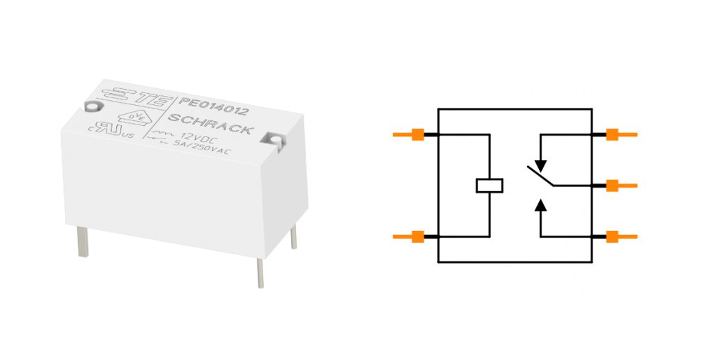
| Pin Number | Pin Name | Function Description |
|---|---|---|
| 1 | A1 | Wire terminal 1, connected to DC voltage (power input) |
| 2 | A2 | Wire terminal 2, connected to DC voltage (power input) |
| 3 | C (Common) | Common terminal, connected to external circuit, usually for switching |
| 4 | NO (Normally Open) | Normally open terminal, when the switch is activated, connects to common terminal |
| 5 | NC (Normally Closed) | Normally closed terminal, when the switch is activated, disconnects from common terminal |
When working with the relay, here are some key points to keep in mind:
Coil Terminals (A1 and A2):
These are where you connect the DC voltage source. When voltage is applied, the relay’s internal contacts will switch. Make sure the input voltage matches the relay’s rated voltage to avoid damaging the relay or causing it to malfunction.
Contact Terminals (C, NO, NC):
-
C (Common): This is the common contact, typically connected to the signal or power path. It will connect to either NO or NC, depending on whether the relay is activated.
-
NO (Normally Open): This contact stays disconnected from C when the relay is off. Once activated, it will close and connect to C.
-
NC (Normally Closed): This contact connects to C when the relay is off. When the relay is activated, it disconnects from C.
When connecting to your circuit, make sure to select the correct NO or NC contacts based on whether you want the circuit to be open or closed when the relay is activated. Always ensure the relay coil is properly protected and that your power supply is suitable for the relay’s requirements.
Pe014012 Equivalent Relay
| Parameters | PE014012 | PE013012 | PE015012 | PE034012 |
|---|---|---|---|---|
| Contact Configuration | 1 Form C (CO) | 1 Form C (CO) | 1 Form A (NO) | 1 Form A (NO) |
| Rated Voltage | 12V DC | 12V DC | 12V DC | 12V DC |
| Rated Current | 5A (Form C) | 5A (Form A) | 5A (Form A) | 6A (Form A) |
| Rated Switching Voltage | 250VAC | 250VAC | 250VAC | 250VAC |
| Max Switching Power | 1250VA | 1250VA | 1000VA | 1500VA |
| Mechanical Life | >15×106 operations | >15×106 operations | >15×106 operations | >15×106 operations |
| Environmental Temperature Range | -40°C to +85°C | -40°C to +85°C | -40°C to +85°C | -40°C to +70°C |
| Package Type | THT PCB | THT PCB | THT PCB | THT PCB |
When choosing a replacement relay, here are a few things to keep in mind:
PE014012 vs PE013012:
Both relays have the same contact configuration and ratings, but the main difference is in the contact material. PE013012 uses AgSnO2, while PE014012 uses AgNi 90/10, which is better for high-durability and conductivity applications.
PE014012 vs PE015012:
PE015012 is a Form A relay (Normally Open) with a 5A rating. If your setup needs a Normally Open contact, PE015012 is a good choice for replacement.
PE014012 vs PE034012:
PE034012 handles higher currents (6A) and power (1500VA), making it suitable for higher-power applications. Even though it has a different contact configuration (Form A), it can still work as a replacement for higher current needs.
What to Keep in Mind:
-
Contact Type: Make sure the relay’s contact type (Form A/CO) matches the original to avoid issues.
-
Ratings: Check that the relay meets your voltage and current requirements.
-
Mechanical Life: Ensure the replacement relay has a similar lifespan to avoid premature failure.
-
Temperature Range: Select one that works within your application’s temperature range.
Pe014012 Relay Driver Circuit
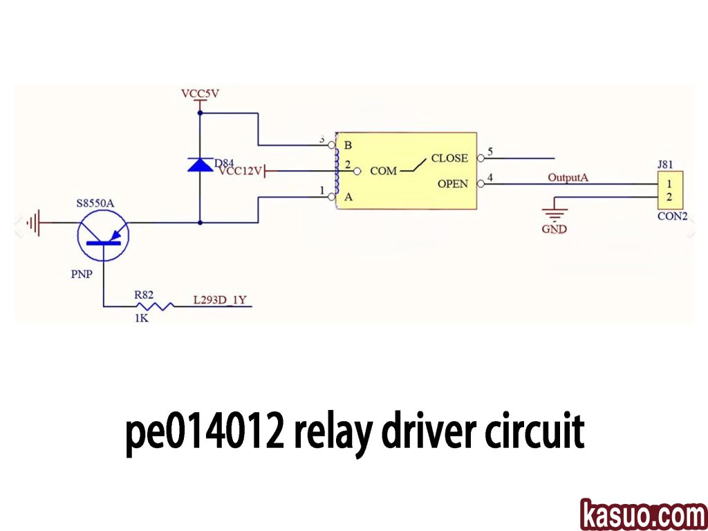
This relay driver circuit uses the PE014012 relay to control a load, and here’s a simple breakdown of how it works:
Key Components:
-
S8550A PNP Transistor: This acts as the switch to activate the relay. The base connects to the input signal via a 1kΩ resistor, and when triggered, it allows current to flow through the relay coil.
-
D84 Diode: Protects the circuit from voltage spikes caused by the relay coil when it turns off.
-
PE014012 Relay: The relay controls the load using its normally open (NO) contacts. When the relay is activated, the NO contacts close, allowing current to flow to the load.
-
L293D Motor Driver: This chip drives motors or other loads, working with the relay to switch the current flow.
How It Works:
When the input signal triggers the transistor, it completes the circuit, powering the relay coil. The NO contacts close, activating the load. The diode ensures no damaging voltage spikes affect the circuit.
This setup efficiently controls high-power loads while protecting your circuit from electrical noise and current backflows.
Pe014012 Load Switching Diagram
When setting up a load switching circuit with the PE014012 relay, here are the key components you’ll need:
-
Relay (PE014012): This is used to control the load. The normally open (NO) contacts will usually be the ones that complete the circuit when the relay is activated.
-
Control Signal: You’ll be using a signal from a microcontroller or a switch to trigger the relay.
-
Transistor Driver: Typically, an NPN transistor like the 2N2222 will control the relay coil. It gets its signal from the control input and switches the relay on and off.
-
Diode: A diode, such as the 1N4007, will be connected across the relay coil to protect your circuit from any voltage spikes when the relay is turned off.
-
Load: This could be anything from lights to motors, depending on what you’re switching.
Make sure to connect everything properly, and you’ll have a solid setup to control your load effectively!
Pe014012 For Hvac Control
If you’re using the PE014012 relay in an HVAC system, here’s how it works and why it’s so useful:
-
What it does: The relay helps control key components like the compressor, fan, and heater. It turns these on or off based on signals from your thermostat or microcontroller.
-
How it fits into the circuit: You’ll connect a microcontroller, like an Arduino, to a thermostat. The thermostat reads the temperature and sends a signal to the microcontroller. The microcontroller then triggers the relay to control HVAC components.
-
Advantages: The PE014012 is compact and reliable, making it perfect for HVAC systems where space is tight. It also uses a low 5V coil voltage, which is easy to integrate into low-voltage systems.
Just make sure the relay’s contact rating matches the current needed by your HVAC components, and don’t forget to add a flyback diode to protect against voltage spikes!
Pe014012 Relay Socket Layout
When you’re working with the PE014012 relay, here’s a quick rundown of the typical pin layout and what each pin does:
-
Pin 1 (Coil+): This is the positive side of the relay coil, usually connected to a 5V power supply.
-
Pin 2 (Coil-): This is the negative side of the coil, which goes to ground.
-
Pin 3 (NO – Normally Open): This contact is open by default but closes when the relay activates.
-
Pin 4 (NC – Normally Closed): This one is closed by default and opens when the relay is triggered.
-
Pin 5 (COM – Common): The common contact, where you connect either NO or NC to control the load.
Make sure you connect the coil pins to your control circuit with a 5V supply. When the relay is activated, it will switch between the NO and NC pins to control your load.
Just a heads-up: always check the current and voltage ratings to ensure the relay can handle your load. If you need a wiring diagram or further help, feel free to ask!
[e014012 Automotive Relay Application
The PE014012 relay is super useful in cars for controlling various electrical systems like lights, fans, power windows, seat heaters, and more. It lets you control high-power devices with a low-current signal, making it ideal for automotive applications. Here’s how it works:
-
Lighting: It controls headlights, fog lights, and taillights. Instead of running heavy current through switches, the relay keeps things safe by handling the high-power load.
-
Air Conditioning: The relay helps turn on the AC compressor and fan, saving energy and ensuring smooth operation.
-
Power Windows: It controls the motors that raise and lower the windows when you press the button.
-
Seat Heaters: On chilly days, the relay helps power the seat heater when you press the button.
-
Fans: It manages cooling fans, ensuring the engine stays at a safe temperature.
It’s a small but crucial component in keeping your car’s electrical systems running smoothly!
More Like This
Also Add to Cart

TQ2SA-24V
Panasonic Electric Works

G3VM-21ER
Omron Electronics Inc-EMC Div

AQZ102D
Panasonic Electric Works

HFD4/24-SR
HF(Xiamen Hongfa Electroacoustic)

AQY214SX
Panasonic Electric Works

ASSR-1410-503E
Broadcom Limited

DSP2A-DC24V
Panasonic Electric Works

S202S02
Sharp Microelectronics

PF240D25
Sensata-Crydom
PE014005
TE Connectivity Potter & Brumfield Relays

IM41GR
TE Connectivity

LH1540AABTR
Vishay Semiconductor Opto Division
Related Products

VO1400AEF
Vishay Semiconductors

AQY221N2V
Panasonic Industrial Devices
TLP172AM
Toshiba
TLP172GM
Toshiba
TLP3123
Toshiba
TLP175A
Toshiba
TLP240A
Toshiba
TLP3122
Toshiba
TLP3341
Toshiba

IM06DGR
TE Connectivity

G6K-2F-Y-DC5
Omron Electronics

V23026D1021B201
TE Connectivity / Axicom
G6A-274P-ST-US
Omron Electronics

FTR-B4GA4.5Z-B05
FCL Components

PCN-124D3MHZ
TE Connectivity

6-1415537-5
TE Connectivity

PCFN-112D2M
TE Connectivity

FTR-J2AK012W
FCL Components

712-12
Teledyne Relays

FTR-B3GA4.5Z-B10
FCL Components
IM41GR
TE Connectivity

FTR-G1CN012W1
FCL Components
HFD4/24-SR
HF(Xiamen Hongfa Electroacoustic)

G6K-2F-Y-5V
Omron Electronics

HFD4/5-S
HF(Xiamen Hongfa Electroacoustic)

RY12W-K
FUJITSU

HFD4/3
HF(Xiamen Hongfa Electroacoustic)

JV24S-KT
FUJITSU

SLA-12VDC-SL-A
Ningbo Songle Relay

SRE-12VDC-SL-2C
Ningbo Songle Relay
Please send RFQ , we will respond immediately.
