What is a 555 Timer? Definition, IC Pinout, Operating Modes, and Applications
Author:admin Date: 2025-05-26 06:38 Views:801
Introduction
The 555 timer is a popular integrated circuit used for multiple timing applications. Such includes generating pulses, working as an oscillator, creating delays, and more. The 555 timer circuit is popular because of its reliability, affordability, and simplicity. Since it can be configured into various modes, it is even more versatile.
555 Timer IC Circuit
The 555 timer circuit clearly shows how the IC circuit is set up and can explain how it works. Below is a circuit showing the block diagram of a 555 timer.
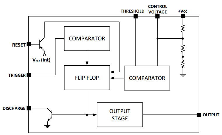
555 Timer IC Block Diagram
From the circuit above, you get several components that work together to realize the performance of the IC.
The circuit has two comparators. Their job is to compare the trigger voltage and the threshold pins.
We also have the flip-flop in the circuit. Its operation depends on the output of the comparators, which in turn determines the output pin state.
The discharge transistor also allows for precise timing control through discharging an external capacitor.
The output pin offers a push-pull output, which means it can source or sink the current.
555 Timer IC Pinout
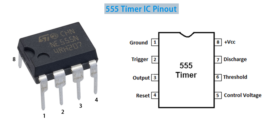
The 555 timer pin configuration helps us better understand what each pin does. Below is a detailed description of the pin configuration of the 555 timer.
| Pin | Name | Use |
|---|---|---|
| 1 | GND (Ground) | Ground reference, low level (0V) |
| 2 | TRIG (Trigger) | It is the negative input for comparator no. 1 |
| 3 | OUT (Output) | Output pin of the timer |
| 4 | RESET | Used for resetting the internal flip-flop states |
| 5 | CTRL (Control) | Controls access to the internal voltage divider |
| 6 | THR (Threshold) | Threshold voltage |
| 7 | DIS (Discharge) | Used to discharge a capacitor in intervals |
| 8 | Vcc | Positive voltage supply |
555 Timer Features
The pinout for a 555 timer helps us see several features to expect with this circuit. Understanding its features can be vital for handling 555 timer projects.
Adjustable Timing
External capacitors and resistors allow precise control over the pulse duration and oscillation. This means better interval timing with easy adjustment options.
Wide Range of Voltage Supply
The 555 timer can operate over a wide range of voltage supplies, including 4.5V to 15V. It can even reach 16V sometimes. This allows for the use of such a circuit for various applications with varying voltage levels.
Handles High Output Current
The output pin can source or sink current up to 200mA. Such a feature makes working with LEDs, small motors, and other electronic devices possible.
Easy to Use
Compared to similar ICs, the 555 timer chip is generally easy to use. You can configure and integrate it into different circuits. Even beginners will have an easy time working with it.
Operating Temperature
The 555 timer’s normal operating temperature is 0 to 75 degrees C, which is okay for most applications. Power dissipation is also kept to a minimum to help maintain the operating temperature low for effective performance.
555 Timer Operating Modes
Looking at a 555 timer datasheet, you will come across various key information about the IC. It may also include the operating modes. For such an IC, you get three main operating modes. They include astable, monostable, and bistable. Each type of operating mode has its own applications because of the output it generates.
Astable Mode
This is also called the free-running oscillator mode since time acts as an oscillator. Since there is no external trigger, you end up with a continuous square wave output.
The external capacitors and resistors control the frequency and duty cycle of the output.
Typical applications for this mode include logic clocks, timing circuits, and pulse generation.
If you need a constant stream of pulses, this is the mode you should use. An example is generating microprocessor clock signals.
Monostable Mode
The monostable or one-shot mode is achieved when the 555 timer produces a single pulse trigger input response.
The width of this output pulse largely depends on the external capacitors and resistors. It is also trigger pulse independent.
This type of mode can be used for pulse stretching, timers, and missing pulse detection. It is suitable for applications that need a pulse with a specific duration as a response to a single trigger.
Bistable Mode
This is also known as the flip-flop mode. It has the high and low stable stages, and trigger pulses toggle between these two states.
The mode makes the unit work as a flip-flop, and the output will be either low or high depending on the applied trigger signal.
It is used for applications that need a state storage function or a memory element. It can be used for simple logic gates or switch debouncing.
Applications of the 555 Timer
The 555 timer circuit diagram is handy for various applications. Below is what you can expect from such an IC.
- Used for creating precise time delays before a certain application occurs. It could be triggering a light in the case of traffic control after a set period.
- Suppose you need a single pulse or a continuous stream of pulses. Such a feature makes it key in controlling other circuits.
- Control systems such as flashing LEDs, alarm systems, and motor control need this IC. Blinking LED circuits can indicate status or provide decorative lighting.
- Other applications for this circuit include logic probes, temperature measurement, analog frequency meters, waveform generators, and more.
How to Troubleshoot a 555 Timer
Sometimes, the 555 timer circuit projects are not working as expected. This might require troubleshooting to understand what could be the issue. Here are a few things you may consider.
- Check the power supply. Is the voltage within the recommended range? This is usually from 4.5V to 16V.
- How about the resistors? Make sure that the resistors have the correct values depending on the circuit design. If you have a faulty resistor, then it might lead to incorrect timing and sometimes circuit failure.
- The capacitors can also determine how well the circuit works. First, check the polarity to see if it is done right. You can still test the capacitor to ensure it is not shorted or faulty.
- How is the 555 timer wired? You must get it right. The last thing you want is incorrect wiring, which can lead to loose connections or bad functionality. Always check for any breaks or damage to the wires.
Conclusion
The 555 timer chip projects are easier to achieve because the IC is easy to work with. So long as you understand how it works, you will have an easier time working with it. The timer 555 circuit comes with various operating modes. These modes make it possible to adapt the IC to your applications. That is why you can find it having many applications, such as generating clock signals, trigger, and much more.
Please send RFQ , we will respond immediately.
Frequently Asked Questions
Is the 555 timer accurate in its performance?
It depends on the option you pick. The standard version is good for basic applications as it may be affected by supply voltage and temperature. However, you can opt for the CMOS version, which is more stable in performance.
Can you cascade the 555 timers?
Yes. It is possible to do so if you need to produce complex circuits depending on the application. Such circuits are often used for complex timing sequences.
Where can you buy a 555 timer IC?
The 555 timer IC can be found in various electronics stores. You can also find them on marketplaces such as Amazon, where they are very affordable.