Expert Guide to Thyristors: Working, Types, and Applications
Author:admin Date: 2025-11-05 08:38 Views:145
Introduction
A thyristor is a four-layer semiconductor device used as a high-power electronic switch in various types of circuits. It is a bistable switch, which means it has only two stable states (on or off). A small current is applied to the gate or third terminal to turn trigger the switch; however, a different mechanism is used for turning off thyristors.
This guide looks into more than just thyristor definition to ensure you can get the best understanding of how thyristors work, types, applications, and much more.
The Structure and Working Principle of a Thyristor
We have already established that a thyristor has four layers. Such include PNPN structure, which now creates three P-N junctions.
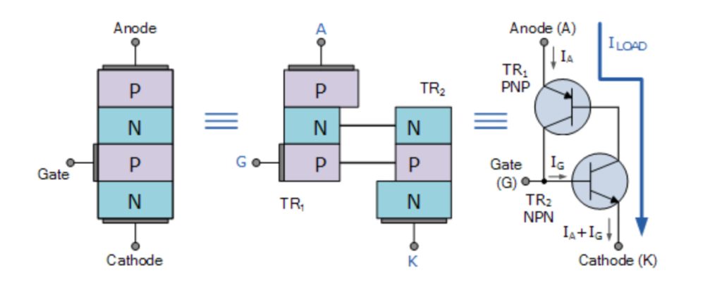
Thyristors have three terminals, including:
- Anode (A): This is the positive terminal connected to the outer P-layer
- Cathode (K): This is the negative terminal connected to the outer N-layer
- Gate(G): This is the control terminal connected to the inner P-layer that is closer to the cathode.
Working Principle
A thyristor comes with three modes of operation. These modes depend on the bias applied across the terminals and the gate signal.
- Forward blocking mode
This is also the OFF state. In this case, a positive voltage is applied to the anode, so junctions 1 and 3 are forward-biased, while junction 2 is reverse-biased.
Junction 2 is controlled by the gate signal, which is not yet available. This means junction 2 acts as an open circuit, which prevents significant current flow. At this point, the thyristor is OFF and blocks forward voltage.
- Forward conducting mode
This is the ON state of the thyristor. In this case, a small positive current is applied to the gate terminal. The gate current provides the base current required to close junction 2.
Think of it as two transistors connected. So, you have a PNP transistor and an NPN transistor. The collector current of the NPN feeds into the base of the PNP, creating a regenerative feedback loop.
This regenerative action drives both resistors into saturation, creating a low-resistance path between the anode and the cathode. That is how the thyristor latches into the ON state.
Once the latching process is done, the gate signal can be removed. The thyristor continues to conduct until the anode current drops below the holding current value.
- Reverse blocking mode
This happens when the anode of the thyristor is made to be negative relative to the cathode. This means junctions 1 and 3 are reverse-biased.
Being reverse-biased prevents current from flowing. The thyristor now behaves like a reverse-biased diode. It will remain in the OFF state.
Applications of Thyristors
Thyristors can generally be used in high-power electronic switches to control large currents even with a small trigger signal. Here are some of the key applications of thyristors.
Motor Control
Thyristors are widely used to regulate the speed of both direct- and alternating-current motors.
In DC motor control, the rectifiers controlled by thyristors vary the voltage supply to the motor’s armature. This is what controls its speed. Also, an AC input voltage is converted into a variable DC voltage through the adjustment of the thyristor’s firing angle.
In AC motor control, thyristors vary the voltage applied to the AC motor, controlling its torque and speed. You can also get them in more complex applications where inverters and thyristors are used to create variable-frequency drives for precise AC motor control.
Power Converters
Thyristors are also important components in various power conversion applications because they can switch large amounts of power efficiently. For example, they can be used in combination with rectifiers, inverters, and cycloconverters for advanced power converters.
In phase-controlled rectifiers, thyristors are used to convert AC power to variable DC power. This power is now used for DC voltage applications such as battery charging systems and DC motor drives.
High-voltage DC transmission
HVDC converter stations use thyristors to transmit electricity over long distances efficiently.
The thyristors are used in AC-to-DC conversion, where high-voltage AC is converted to DC. It is also used for DC-to-AC conversion. Thyristors are highly efficient for bulk power transfer.
Solid-state Relays
The SSRs use thyristors, such as TRIACs and SCRs, as switching components rather than mechanical contacts found in traditional relays.
Since there are no moving parts, expect the SSRs to be faster and quieter. They also have a longer lifespan than electromechanical relays.
SSRs are common in industrial automation, HVAC systems, and other applications that require frequent, reliable on/off switching of high-power loads.
Lighting and Heating Control
Thyristors are also commonly used to control the power delivered to resistive loads, such as heating elements and lamps.
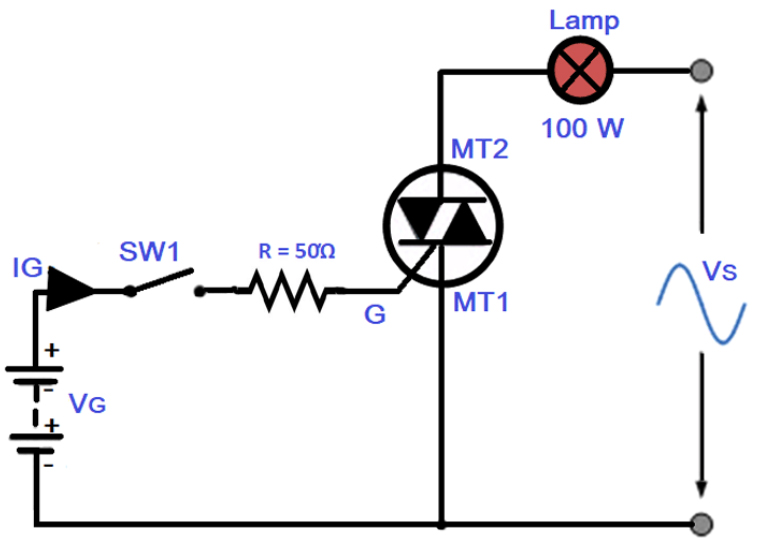
For example, light dimmers use a TRIAC thyristor for controlling the brightness of bulbs. This is done by adjusting the thyristor’s firing angle, which varies the average power delivered to the lamp.
Temperature control can also be achieved using thyristors. This is where they regulate the power supplied to the heating elements, thus maintaining a stable temperature.
Different Types of Thyristors and Their Uses
- Silicon-Controlled Rectifier (SCR)
This is the most basic and common type of thyristor in the market. It is mainly used for controlled and unidirectional switching.
SCR has three terminals and conducts in only one direction. Once it is latched into the ON state, it requires the anode current to drop below a specific value for it to turn off.
Uses: AC power control, motor speed control, protective circuits, and lighting dimmers.
- Gate Turn-Off (GTO) Thyristor
This type of advanced thyristor can be turned on and off via its gate terminal. This addresses the primary limitation of using an SCR.
The GTO thyristor turns ON when a positive gate signal is applied and OFF when a large negative current is applied to the gate. It is a fully controllable switch.
Uses: Used in high-speed switching applications where controllable turning off is required. Such include inverters and motor drives.
- Triode for Alternating Current (TRIAC)
This is a bidirectional thyristor that conducts current in both directions of the AC waveform. It works like having two SCRs connected in inverse parallel, and having a single gate terminal controlling conduction in both directions. The gate pulse triggers the thyristor and turns off at the end of each half-cycle when the current drops to zero.
Uses: household light dimmers, temperature regulations, and fan speed controllers
- Light-activated SCR (LASCR)
This is a type of thyristor that can be triggered by a light source rather than an electrical gate signal. So, when a light beam strikes the sensitive gate region, it excites the electron-hole pairs, which trigger the thyristor into conduction.
Uses: High voltage and high current applications, including static VAR compensation and HVDC transmission systems.
- MOS-controlled Thyristor (MCT)
The MCT is a hybrid device that features MOSFETs in its gate structure to provide complete ON/OFF control via a voltage signal. The MCT offers the high-voltage and high-current capabilities of a thyristor with the fast, low-power control of MOSFETs.
Uses: DC-DC converter, induction heating, and inverters.
Thermal Management in Thyristors
Effective thermal management is vital for the operation and longevity of the thyristors. This is especially when used in high-power applications.
Thyristors, like other semiconductors, are susceptible to thermal runaway. This is a self-reinforcing process in which increased temperature leads to higher leakage current. This even raises the temperature further.
During the ON state, thyristors have a small but significant voltage drop. This results in high power dissipation and heat generation when conducting high currents.
As expected, performance will degrade with increased leakage currents. High junction temperatures increase turn-off times, affecting overall device performance and reliability.
Cooling Methods
It is possible to prevent thermal issues by using a wide range of cooling techniques. The best method depends on the device’s power rating. Here are the primary cooling methods.
- Natural air cooling – For this type of cooling, the heat is dissipated from the thyristor’s heat sink into the surrounding air with the help of natural convection and radiation. It is best suited for low-power applications where heat generation is small.
- Forced air cooling – This cooling technique involves having fans or blowers forcing air over the heat sink fins. This increases heat dissipation and reduces the need for a large heat sink. You can use it for medium power applications where passive cooling is insufficient.
- Liquid cooling – A liquid coolant, such as oil or water, is circulated through the cooling plate or heat sink, which is in direct contact with the thyristor. The liquid’s role is to absorb the heat and carry it to a heat exchanger.
Common Thyristor Failures and How to Prevent Them
Thyristor failure can be caused by several factors that, if addressed early, can prevent it. Here is what you can expect with thyristor failures.
- Thermal failure or overheating
Excessive heat generation when the thyristor is ON can lead to overheating and eventually failure. It is therefore important to implement appropriately sized heat sink or ensure adequate airflow to ensure effective cooling.
- False triggering
Sometimes the rate of voltage change across the thyristor is too high, then the internal junction capacitance may pass enough displacement current, which ends up triggering the device even without the gate signal. Such leads to uncontrolled conduction.
Using a resistor-capacitor network in parallel with the thyristor will limit the voltage rise rate. The capacitor slows the voltage change, and the resistor limits the capacitor’s discharge current whenever the thyristor turns on.
- Turn-on failure
During the turn-on phase, the conductive area of the thyristor spreads gradually from the gate. However, if the anode current rises too fast, it can lead to hot spots, which damage the silicon.
To resolve this, connecting inductors in series with the thyristors limits the rate of current rise during the turn-on phase, ensuring the current speeds are uniform across the junction.
How to Test a Thyristor Using a Multimeter: Step-by-Step Guide
Here is how you can test a thyristor to see if it is in good working condition or not.
- Make sure the power is turned off before you start testing the thyristor.
- Set the multimeter to the resistance mode.
- Check the gate-to-cathode junction by placing the red probe on the gate and the black probe on the cathode.
- You should expect low resistance, indicating the PN junction is intact. Reverse the probes. Expect a very high resistance since the junction is now reverse-biased.
- If you get low resistance or a beep in both directions, it means the junction is shorted.
- Next, check the anode-to-cathode junction in the OFF state. Connect the red probe to the anode and the black probe to the cathode.
- Expect the multimeter to show very high resistance or an open loop reading.
- Reverse the probes and check how it behaves. Expected reading would be very high resistance as well. However, if you get a low resistance or continuity reading in either direction, it indicates that the thyristor is shorted or has failed.
- You can also test with the thyristor in the ON state. Keep the red probe on the anode and the black probe on the cathode. Expect a high resistance reading.
- Go ahead and touch the red probe to the gate, then return it to the anode. This brief contact with the gate provides the signal to turn on the thyristor.
- At this point, the multimeter should show low resistance, indicating that the thyristor is in the ON state and latching.
- If the resistance remains high even after the gate pulse is applied, then the thyristor is faulty.
Conclusion
A thyristor is crucial in many applications, as we have seen above. For that reason, it is expected that you may have used one already. It is crucial to always use the right thyristor for the job to ensure optimal performance. Also, proper cooling is necessary to avoid thyristor performance degradation. Keep in mind the thermal management tips to keep the thyristor within the right temperature operating range.
Please send RFQ , we will respond immediately.
Frequently Asked Questions
What are the main applications of thyristors?
Thyristors are widely used in applications such as power control systems, converters and inverters, HVDC transmission, battery charging, and overvoltage protection circuits.
Is there a difference between a thyristor and a transistor?
A thyristor works as a latching device, meaning once it is turned on, it stays in the ON state until the current falls below the holding levels. As for a transistor, it can be turned on and off depending on the input signal.
Can you use thyristors in DC circuits?
Yes. Thyristors can be used in DC circuits for various applications; however, they cannot be automatically turned off. As such, forced communication is a technique used to turn off the thyristor by temporarily reducing the current below the holding value.