How the Inverting Operational Amplifier Works: Circuit, Working Principle & Applications
Author:admin Date: 2025-07-21 06:33 Views:567
Introduction
An inverting operational amplifier is a type of op-amp circuit configuration where we have the output voltage inverted 180 degrees out of phase, and it is amplified compared to the input voltage. This type of circuit uses negative feedback to help with achieving a stable gain. The gain is determined by the resistors’ ratio in the feedback and input paths.
The inverting and non-inverting operational amplifiers are some of the important circuit configurations for various electronics. Today, we will focus more on the inverting operational amplifier circuit to show you how it works in detail and how best it can used for various applications.
The Basic Operating Principle of an Inverting Op-Amp
The inverting operational amplifier amplifies the difference between its two input terminals. How it does this makes it stand out for several electronic applications.
The core principle is in the negative feedback. The output voltage of this op-amp is fed back to the negative or inverting input terminal of the inverting operational amplifier. This type of mechanism is vital for stabilizing the amplifier and have a predictable gain.
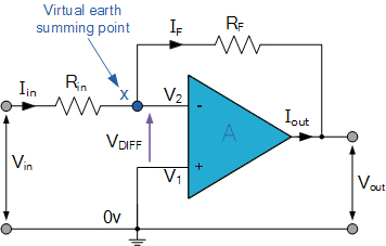
The inverting input terminal of the op-amp is called the virtual ground, even if it is not directly connected to ground. This is because the feedback mechanism keeps the inverting input voltage close to the non-inverting input voltage, which is ground.
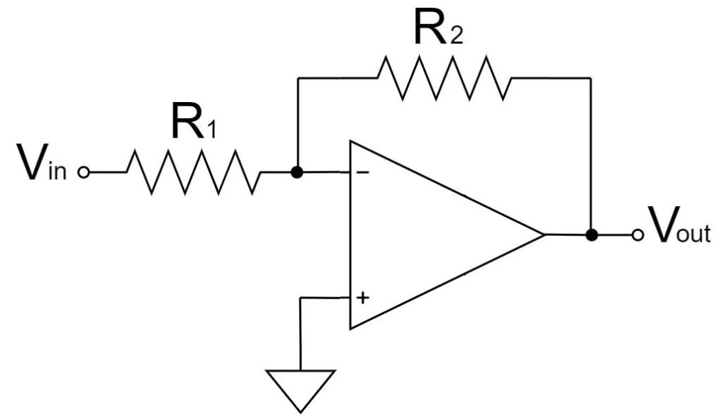
The input voltage is directed to go through the input resistor (R1) to the inverting terminal. As for the output voltage, it is fed back to the inverting terminal by passing through a feedback resistor (R2).
To get the voltage gain of the inverting amplifier, you have to get the ratio of the two resistors. So, the gain is -(R2/R1). Having the negative sign shows phase inversion.
How about the current flow in an inverting operational amplifier? Since there is high input impedance in the op-amp, no current flows to the input terminals. As such, the current flowing through R1 is the same as that in R2.
Parameters of an Inverting Operational Amplifier
There are a couple of parameters that determine how an operational amplifier as inverting amplifier works. Here is what to expect.
– Voltage gain formula
The voltage formula is Av = -Rf / R1. The Rf in this formula is the feedback resistor, while R1 is the input resistor. However, why the negative sign? This sign indicated that the output signal is inverted and 180 degrees out of phase relative to the input.
– Input and output impedance
The input impedance of an inverting op-amp is the same as the input resistor. This is because the inverting input terminal works as the virtual ground.
As for the output impedance, we expect it to be very low. Ideally, it should be near zero because of the negative feedback.
– Frequency Response
The frequency response is important to keep in mind as it describes how the amplifier gain changes with frequency. In this case, expect to get a gain bandwidth product (GBWP) relationship like other op-amp configurations.
– Bandwidth
The bandwidth is the range of frequencies of the inverting op-amp where the amplifier provides a usable gain. How do you get the bandwidth? In this case, the bandwidth is inversely proportional to the gain. So, BW = GBWP / (1+ |Av|). Some sources state that BW = GBWP / (R1/RF). These two formulas should help you determine the inverting op-amp bandwidth.
Applications of an Inverting Operational Amplifier
There are many advantages of inverting operational amplifier based on the number of applications it can handle. Here are several applications of the inverting operational amplifier.
As an inverting amplifier
This is the most basic application where the input signal is inverted and amplified by a factor. This gain is determined by the ratio of feedback and input resistors.
Summing Amplifier
Multiple input signals can be added together in an inverting operational amplifier. Each input depends on its corresponding resistor value.
Transresistance Amplifier
In this case, the inverting op-amps works as a current-to-voltage converter. For example, it can be used in photodiodes or other sensors that can output a small current. The feedback resistor is used to determine the output voltage.
Filters
The inverting operational amplifier can also work in filter designs. This includes the high-pass, low-pass, and band-pass filters. When used in such applications, they introduce a phase shift in the filter stages. This can be a pro or con, depending on how it is used.
Signal Processing
The inverting op-amps can be used for signal processing applications as well. Such include integration and differentiation. The output signal will be proportional to the derivative or integral of the input signal.
It is expected that the inverting operational amplifier may have many other applications. These are just a few that we can mention for now. It all depends on how you configure it to work in your circuit.
Pros and Cons of an Inverting Op-Amp
Pros
- It is to get the gain of the op-amp as it is based on the ratio of the feedback and input resistor
- Signal inversion of up to 180 degrees out of phase may be useful for some applications.
- The inverting op-amps is generally stable compared to a non-inverting op-amp.
- The input impedance will primarily be determined by the input resistor, making it easier to control it.
- Expect the inverting operational amplifier to have many applications because it is versatile. This includes being in summing amplifiers and transresistance amplifiers.
Cons
- The 180-degree phase shift may not always be good for some applications
- It will also come with a lower common-mode rejection ratio. This means they cannot effectively reject common-mode noise.
- The feedback resistor is connected to the output. This may lead to increased noise compared to the non-inverting configurations.
How to Simulate and Test an Inverting Operational Amplifier
It is possible to simulate the function of inverting operational amplifier with a software so that you can adjust it accordingly before implementation. Here is how you would do it.
- Choose the appropriate simulation software. The common options for this process includes Multisim, Cadence OrCAD PCB Designer, or LTspice.
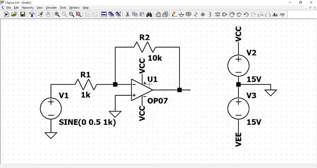
- Build the circuit: Place the op-amp, signal source, and resistors on the simulation workspace. Have them connected accordingly, depending on what you want to achieve.
- Set the component values: This is key as you get to choose the appropriate resistor values for the designed gain. Adjust accordingly to get the right gain.
- Configure the simulation: Here, you choose the input signal. It can be a sine wave with a specific amplitude and frequency. Also, pick the simulation parameters as well such as the transient analysis or frequency response.
- Run the simulation: Once you have configured the circuit properly, run the simulation and observe the waveform or compare it to the expected results. You can adjust the parameters accordingly to achieve the desired output.
Troubleshooting Tips for an Inverting Op-Amp
With the definition of inverting operational amplifier, you have a better understanding of how it works. However, it is possible you may face a few issues with the inverting op-amp. Here is how to troubleshoot it.
Power Supply Issues
It is possible there could be an issue with the power connections. The solution is to verify the power connections, making sure the input is correctly connected.
Input Signal
Is there a signal presence at the input? Start by checking if the input signal is present. It should also be of the correct amplitude and frequency. Using an oscilloscope can help verify the input and output signals in the circuit.
Also, check for the input impedance. It should also be within the appropriate range based on the input signal.
Feedback Resistor
Confirm that there is a feedback path from the output to the inverting input. This is important for the proper performance of the inverting operational amplifier. Double-check the resistor values so that you can have the desired gain.
Also, check if the resistors are working correctly. If not, you may have to replace them.
Op-Amp Behavior
The way the inverting op-amp behaves often determines if it is working correctly or not. It is important to verify that the output voltage is within the right range based on the gain and power supply voltage.
Sometimes, there can be saturation in the op-amp because the input signal is too large or the gain is too high. Make sure to check the input signal and resistor values.
PCB Layout
It is important to have good PCB layout practices in mind when designing and setting up the inverting op-amp. This is important to avoid issues such as noise, crosstalk, or instability.
Proper grounding is often underestimated, but it is important to keep in mind if you want the best performance with a stable op-amp operation.
Conclusion
Looking at the inverting configuration of operational amplifiers, we can see how they are different from the non-inverting. This comes with specific applications where such a design comes in handy. Examples include signal processing in various electronic devices. It is advisable to simulate the inverting operational amplifier first with software before building it physically. This helps in minimizing the errors and only implementing when you are sure it works as expected. Keep in mind the troubleshooting tips above to end up with a working inverting op-amp.
Video: Inverting op-amp circuit
Please send RFQ , we will respond immediately.
Frequently Asked Questions
How does an inverting op-amp differ from an non-inverting op-amp?
The main difference is where the input signal is connected to. In an inverting op-amp, the input is applied to the negative terminal and its output is inverted. As for the non-inverting op-amp, the input is applied to the positive terminal and its output remains in the same phase as the input. This also means the gain formulas also differ.
Why is it important to ground the non-inverting input in an inverting op-amp?
Grounding the non-inverting input is important to create a reference point. This allows the op-amp to maintain virtual ground at the inverting input, ensuring there is stability and linear operation.
Why can the output of the inverting op-amp saturate sometimes?
The output may saturate if the input signal is too large or the gain is too high. This means the output is pushed beyond the voltage limits of the op-amp.