The Ultimate Beginner’s Guide to MOSFETs: How They Work and Where They’re Used
Author:admin Date: 2025-08-06 02:53 Views:824
Introduction
A MOSFET (Metal-Oxide Semiconductor Field-Effect Transistor) is an essential component in modern electronics, commonly used for switching and signal amplification. It features three main terminals: the gate, source, and drain. By applying a small voltage to the gate, the device controls the flow of a larger current between the source and drain terminals.
To better understand this transistor below, we will look more into how MOSFETs work, their types, applications, and many other parameters.
MOSFET Working Principle
A MOSFET functions as a switch that is controlled by voltage. By adjusting this voltage, it manages how much current can pass between the source and drain terminals.
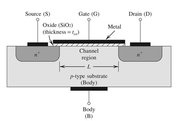
It features three key terminals: Gate (G), Source (S), and Drain (D). The gate is isolated from the channel by a very thin layer of metal oxide, which acts as an insulator.
When a voltage is applied between the gate and the source (VGS), it generates an electric field. This field influences the movement of charge carriers within the channel, either allowing current to flow or blocking it.
The behavior of the channel depends on the type of MOSFET, either N-channel or P-channel, each with its own method of controlling the current flow.
In an N-channel MOSFET, applying a positive voltage to the gate relative to the source (Vgs) draws electrons toward the gate region. This movement of electrons forms a channel that enables current to pass from the drain to the source. Essentially, the device turns on and allows current to flow when the gate voltage is positive.
On the other hand, a P-channel MOSFET operates with a negative gate-to-source voltage. This negative voltage attracts positive charge carriers (holes), creating a path for current to move from the source to the drain. In this case, the transistor conducts when a negative voltage is applied to the gate.
Most MOSFETs are initially off with no channel and require a small voltage to turn on. To create the channel, you will need to apply an appropriate voltage to the gate terminal. When you increase the voltage, the width of the channel increases, which increases the current flow.
Because of how they work, MOSFETs are widely used in electronic circuits that need switching and signal amplification. This is because of their fast switching speed and low power consumption.
They are also fundamental in building digital circuits, power electronics, and many other applications.
MOSFET Parameters
Now that you know the MOSFET meaning, we can shift the focus onto its parameters. There might be many parameters, but these are the main ones.
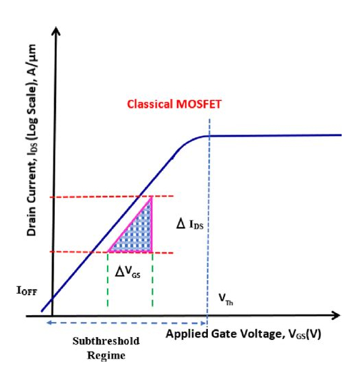
Threshold Voltage
This is the gate-to-source voltage (VGS) at which the MOSFET conducts current between the drain and source. It is an important parameter to note as it can determine the MOSFET’s switching behavior and ensure its proper operation.
Drain Current
This is the current from the drain to the source. It largely depends on the VGS and the other MOSFET characteristics.
Gate-to-Source Voltage (VGS)
We have already referenced this one. It is basically the voltage applied between the gate and source terminals, which controls the on and off states of the MOSFET. You can see it is vital for the switching applications of the MOSFET.
On-Resistance (Rds(on))
This is the resistance found between the drain and source when a MOSFET is fully turned on. A lower on-resistance is more desirable as it helps minimize the power loss and maximize efficiency.
Capacitances
These parasitic capacitances affect the switching speed and overall performance of the MOSFET. Such include the input, output, and reverse transfer capacitances. They will influence how quickly the MOSFET turns on and off.
MOSFET Transfer Characteristics
Many factors define the MOSFET’s transfer characteristics. To understand its behavior in different types of applications, we will examine both the input and output characteristics.
Transfer Characteristics (Input Characteristics)
Cut-off Region
When the VGS voltage is below the threshold voltage, the MOSFET is basically off, and no significant current flows in the channel. In this case, the transistor is an open switch.
Triode Region
In this case, the VGS is greater than the threshold voltage, and the MOSFET starts to conduct. This region is also called a linear or ohmic region because the drain current increases linearly with the increase in drain-to-source (Vds) voltage value. Right now, the MOSFET behaves as if it is a voltage-controlled resistor.
The channel resistance also decreases with the increase in VGS.
Saturation Region
As the Vds value increases, the channel narrows near the drain. This is because the drain current starts to saturate. A further increase in the Vds value will have little to no effect on the drain current. This is now the saturation region.
Output Characteristics
Cut-off Region
It is similar to the transfer curve, and no current flows in the region when the Vgs is less than the threshold voltage (Vth).
Triode Region
In this case, the drain current increases linearly with the increase in the Vds. At this point, the MOSFET behaves like a resistor. Also, the slope depends on the Vgs.
Saturation Region
The drain current becomes constant and largely depends on the changes in Vgs. The MOSFET can be used as a current source in this region.
Types of MOSFETs
Below are the main types of MOSFETs in the market.
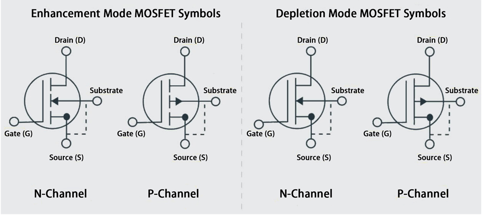
1. Enhancement-Mode MOSFETS
In enhancement-mode MOSFETs, no current flows between the source and drain when the gate terminal has no voltage. Applying a voltage to the gate creates a conductive channel, which enables current to pass through the device.
Expect them to be widely used in switching applications and digital circuits.
2. Depletion-Mode MOSFETs
The depletion-mode MOSFETs are typically on even when no voltage is applied to the gate terminal. Applying the voltage to the gate will reduce or deplete the existing channel. The result is a decrease in current flow.
You would use such MOSFETs in specific applications that need a normally on MOSFET at all times.
3. N-Channel MOSFETs
In the N-channel MOSFETs, the current flow is primarily due to the negatively charged electrons. This channel is created when a positive voltage is applied to the gate terminal or when the gate voltage is reduced (depletion mode).
How these MOSFETs work makes them ideal for applications such as power supplies, inverters, and DC/DC converters.
4. P-Channel MOSFETs
The P-channel MOSFETs current flow is due to the positively charged holes. In this case, a negative voltage has to be applied to the gate terminal to create the P-channel, or when the gate voltage is reduced in depletion mode.
Its applications include high-side switches and load switches.
Applications of MOSFETs
MOSFETs are quite versatile. As we will see below, you are likely to find them in many electronics.
Power Electronics
MOSFETs are important in DC-DC converters. They are used in switching power supplies such as boost, buck, and buck-boost converters, and they efficiently adjust the voltage level of the power source.
They can also be used for motor control to regulate the speed and direction of motors. This is important for applications such as robotics, industrial machinery, automotive electronics, and household appliances such as fans and washing machines.
Signal Amplification
MOSFETs are commonly used in audio amplifiers because they’re capable of managing high-power signals and functioning efficiently at elevated frequencies. You’ll often find them in car stereos, sound systems, and professional-grade audio gear.
MOSFETs also work as transistors in many types of analog circuits, including mixers, filters, and amplifiers. They are used for such applications because of their good linearity and high input impedance.
Digital Logic Circuit
CMOS, short for Complementary Metal-Oxide-Semiconductor, uses a combination of both P-Channel and N-Channel MOSFETs. It’s a fundamental technology behind most modern digital logic circuits. Known for its energy efficiency and fast switching capabilities, CMOS is widely used in microprocessors, memory devices, and various digital integrated circuits.
Advantages and Disadvantages of MOSFETs
Advantages
- High input impedance means the MOSFETs draw very little current from the driving circuit. As such, they are easier to drive and quite efficient in many applications.
- Fast switching speeds make them ideal for high-frequency operations and fast response times in various circuits.
- Manufacturing of the MOSFETs is relatively easy. This leads to a lower production cost, which translates to affordable MOSFETs available for implementing different project types.
- MOSFETs are also voltage-controlled, which makes it easier to achieve precise control.
- MOSFETs offer more power efficiency compared to other transistor types. That is why you would use them to switch applications.
Disadvantages
- A MOSFET as a switch circuit is often susceptible to static electricity. That is why you need careful handling and implement ESD protection measures.
- A MOSFET driver is not recommended for high-voltage applications. It is best to use it in low-voltage, high-current applications.
- The temperature variations easily affect the sensitivity of the MOSFETs. Be careful about the operating temperature to ensure they work correctly.
MOSFET vs. BJT (Bipolar Junction Transistor)
Both the MOSFET and BJT are key transistors used in controlling electrical current, but they differ in terms of operation and characteristics.

The BJT transistor is current-controlled. This means it requires continuous current flow in the base to control the flow of current between the collector and emitter. BJTs also have relatively low input impedance, so they can draw more current from the driving circuit.
BJTs tend to have slower switching speeds than MOSFETs. This makes them less suitable for applications with high frequencies. Still, expect BJTs to offer a higher gain and better fidelity in the linear region of operation. Because of their simpler structure, they will also be less expensive than MOSFETs.
Applications of BJTs include audio amplifiers, digital logic circuits, sensor interfaces, and switching power supplies.
| Feature | MOSFET | BJT |
|---|---|---|
| Type | Field-Effect Transistor | Bipolar Junction Transistor |
| Control Mechanism | Voltage-Controlled | Current-Controlled |
| Power consumption | Lower | Higher |
| Switching Speed | Faster | Slower |
| Input impedance | High | Low |
| Thermal stability | Sensitive to temperature changes | More stable with temperature changes |
| Current handling | Can handle high currents | Can handle lower currents |
| Complexity | More complex | Simple structure |
| Applications | High frequency switching, digital logic, power suppliers | Audio amplifiers, signal amplification |
How to Test and Troubleshoot MOSFETs

A multimeter is a great tool for testing and troubleshooting MOSFETs. Here is how to use it.
1. Identify the terminals
A MOSFET has three terminals: the gate, drain, and source. Before testing, look at the MOSFET datasheet to determine which are the correct terminals. A transistor tester is another alternative for identifying the terminals.
2. Check for shorts
Set your multimeter to a diode or continuity mode.
In the Off State, the gate is isolated, so no voltage is applied to it. Check for continuity between the drain and source. A good MOSFET should show no continuity in such a state.
A small positive voltage is applied to the gate terminal in the ON state. This should turn on the MOSFET, and it should be present when continuity is measured again between the drain and source.
If there is continuity during the off state or there is no continuity in the on state, then the MOSFET is faulty.
3. Gate leakage test
You can also test for leakage at the gate terminal.
Connect the red probe to the gate and the black probe to the drain or source. A good MOSFET shows very high resistance or no continuity because of the open circuit. A low resistance or continuity reading between the gate and the other terminals means there is leakage, and the MOSFET is faulty.
Conclusion
As you have seen above, MOSFETs have many applications based on how they work. With the proper application, they are quite impressive in how they perform. They might have limitations, but they are important in digital electronics today. Since we have covered how to test them, it should be possible to quickly identify issues with the MOSFET and replace it whenever necessary to keep the application working as expected. Also, keep in mind the project requirements to pick the correct MOSFET for it.
Video: MOSFETs Explained – How MOSFETs Work
Please send RFQ , we will respond immediately.
Frequently Asked Questions
How is a MOSFET used in a circuit?
You can use a MOSFET in a circuit for applications such as amplification, switching applications, and many others. It is vital to consider it as part of the circuit design process and implement it correctly.
How is a MOSFET protected from damage?
We recommend using gate resistors for over-voltage protection. Flyback diodes for inductive loads and implement ESD handling precautions.
What happens when too much voltage is applied to the gate?
Too much voltage at the gate terminal can damage the MOSFET, making it unusable for various applications. Always stick to the recommended gate solution.