How A Non-inverting Operational Amplifier Works: A Detailed Breakdown
Author:admin Date: 2025-05-21 07:11 Views:880
Introduction
What Is a non-inverting operational amplifier? How does it work? What are its applications? These are just some of the questions people might have in mind if they are new to operational amplifiers.
A non-inverting operational amplifier is a type of circuit where the output voltage is in phase with the input voltage. In this case, the operational amplifier will amplify the input signal while maintaining its phase, which is the opposite of what you get with an inverting operational amplifier.
It is crucial that you connect the input signal to the non-inverting input of the operational amplifier.
We focus more on the operational amplifier non-inverting below so that you can better understand its working principle and how it works.
Characteristics of Non-Inverting Operational Amplifier
A non-inverting operational amplifier circuit comes with many characteristics that make it a good pick for many uses. Here are notable characteristics you should know.
- The circuit offers phase preservation. This is where the output signal remains in phase with the input signal.
- The non-inverting input terminal is connected to the input source directly, resulting in very high input impedance. The source is minimally loaded, and the input signal remains unaffected.
- The circuit design of this op-amp is simple when compared to other amplifier configurations. It becomes easier to implement.
- With this circuit, you can expect a positive gain. This means the output signal gets amplified without changing its polarity.
- The non-inverting input terminal is vital for adjusting the offset voltage, which is key to improving the circuit’s accuracy.
- Expect a very low output impedance. This makes the circuit suited for driving loads.
How a Non-Inverting Operational Amplifier Works
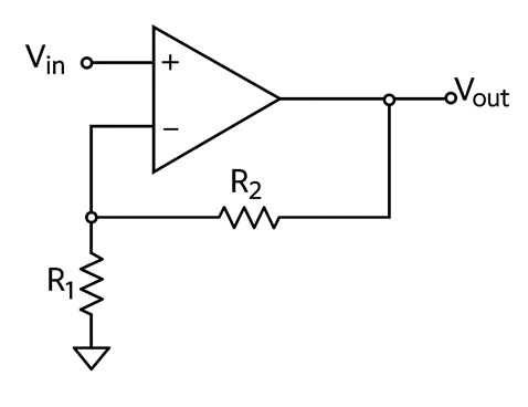
Non-Inverting Operational Amplifier Circuit
We have already established that an ideal non-inverting operational amplifier will amplify the input signal without inverting its polarity. However, how does it work? Below is a detailed explanation of how non-inverting op-amps work to achieve their characteristics.
First, the input signal is applied to the non-inverting input of the operational amplifier. In the circuit, you have the feedback network. It consists of two resistors connected between the op-amp output and the inverting input.
The gain is determined by the ratio of the feedback resistors (R2/R1). So, the gain can be determined by 1 + (R2/R1).
The output voltage will be amplified compared to the input voltage. However, the two will still be in phase, and the feedback resistor ratio determines the gain of the amplified output voltage.
Applications of Non-Inverting Op-Amps
The non-inverting amplifier circuit operation has many applications in electronics. Examples include:
- Amplification where the non-inverting amplifier operationamplifies the input signal while maintaining the phase. This is suitable for applications where the phase shift is unwanted.
- This circuit can also be used to design voltage followers or unity gain buffers. These circuits have high input impedance and low output impedance.
- Active filters can also use this type of circuit. It is expected to be used for low-pass, band-pass, and high-pass filters.
- Voltage regulators could also use such a design, as it helps maintain a stable output voltage despite variations in load conditions.
- Signal conditioning is another good use of non-inverting operational amplifiers. The circuit can filter, scale, or level the signals before they are processed further.
How to Build a Non–Inverting Operational Amplifier Circuit
Now that you know about the non-inverting amplifier applications, next is to see how best to design and build one. Here are the steps you can follow.
- Choose the operational amplifier you will use for the application. Look at parameters such as the slew rate and gain bandwidth product.
- Next, you need to choose the resistor values. To do this, determine the desired gain first. This will help you design the op-amp with the right resistor values to achieve a particular gain.
- Now is the time to build your circuit. Connect the input signal to the non-inverting or positive terminal of the op-amp. Connect the feedback resistor (R2) and the other end of the feedback to the negative or inverting terminal of the op-amp. Also, connect the input resistor to the negative terminal.
- Go ahead to power the op-amp with a suitable power supply.
- Test the circuit to see if it works as expected. Consider applying a sign wave at the input and observe if you get a similar waveform at the output. Use an oscilloscope to visualize the waveform.
Best Practices and Design Tips for Non-Inverting Op-Amps
During the non-inverting operational amplifier configuration, consider a few things to ensure the success of your op-amp. Such include:
Thermal Management
The non-inverting op-amps can generate heat especially while handling high currents or frequencies. It is therefore important to ensure there is better heat dissipation. You can implement thermal pads or heatsinks to prevent heating which affects performance.
Resistor Selection
Your choice of resistor is key to the op-amp’s operation. Avoid using high-value resistors, as they can increase noise or reduce phase margin. Use the standard gain formula to find the right resistor values for the circuit.
Bandwidth Considerations
The bandwidth of a non-inverting amplifier will be limited by the gain-bandwidth product of the chosen op-amp and the circuit gain.
High gains will reduce the available bandwidth, and the slew rate will limit large signal performance. So, check the op-amp datasheet to understand the output swing limitations.
PCB Layout
You should avoid placing capacitive loads directly on the op-amp output. This helps minimize stability issues.
A guard ring can help minimize the stray capacitance effects. If the circuit is meant for precision applications, keep an eye on the layout and how best to route the components to minimize noise and stray capacitance.
Grounding
Grounding is still important for the operation of the operational amplifier. A low-impedance ground plane is recommended for optimal performance and noise reduction.
Inverting vs. Non-Inverting Operational Amplifier
There are several differences when looking at inverting vs. non inverting operational amplifiers. The biggest difference is that inverting amplifiers invert the input signals while the non-inverting does not.
The input impedance for the inverting op-amp tends to be lower than what you get with the non-inverting amplifiers. They tend to have very high input impedance.
The voltage gain of the inverting operational amplifier is negative, while that of the non-inverting amplifiers is positive.
Inverting amplifiers come in handy for applications that need phase shift or signal inversion. You will use the non-inverting amplifiers if the application requires maintaining the phase of the input signal.
Conclusion
The non-inverting operational amplifier is an important circuit design in many applications. You can expect to find it in various devices performing key functions, such as amplifying the input signal without a change in phase. If you decide to design one, keep in mind the various tips we have mentioned above to ensure that the op-amp performs as expected. Always be ready to analyze the circuit and improve it where necessary to achieve the desired results with the operation of a non-inverting amplifier.
Please send RFQ , we will respond immediately.
Frequently Asked Questions
Can the gain of the non-inverting op-amp be less than 1?
No. Since it is non-inverting, the minimum gain will be 1. This occurs when R = 0 and is also known as a buffer or voltage follower.
What makes the non-inverting operational amplifier have a high input impedance?
This is because the input signal is connected to the non-inverting input directly. This leads to drawing negligible current. The result is having a high input impedance good for voltage sensing.
What is the phase relationship between the input and out of a non-inverting op-amp?
The output signal is in phase with the input signal. This means there is no phase inversion, unlike in an inverting op-amp.
Can you use a non-inverting op-amp with AC signals?
Yes. the non-inverting op-amps can work with both AC and DC signals. It all depends on the application and biasing.