Pull-Up Resistors Explained: How They Work and Where to Use Them
Author:admin Date: 2025-07-29 09:00 Views:585
Introduction
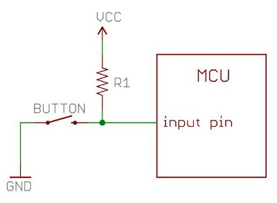
A pull-up resistor is a type of resistor connected between a digital input pin and a positive voltage supply, such as 5V. This is key in ensuring that the input pin can still read the supply voltage even when the switch is disconnected or open. However, why is this the case?
The pull-up resistor is important so that the input does not float to an undefined voltage, which may cause erratic behavior.
You may also come across a pull-down resistor, which we will discuss later. For now, let us focus on the pull-up resistor, why it is important, its common applications, and much more.
Importance of Pull-Up Resistors
Pull-up resistors are important for maintaining a known logic state for a digital circuit. This is especially when working with open collector outputs or switches. Here are more reasons in detail about why pull-up resistors are important.
Prevents Floating Inputs
Digital circuits have high or low logic levels that represent a specific voltage range. When a switch is open, the pin is disconnected from the circuit, thus floating. This basically means the voltage, in this case, is not defined and easily fluctuates.
A pull up resistor keeps the input pin connected to a voltage source. Even if the switch is open, the resistor still pulls the voltage, resulting in a defined logic high state at the input pin.
When this happens, the pin no longer floats, and its behavior becomes more predictable.
Reduces Noise Sensitivity
Floating inputs tend to be highly susceptible to noise, which can lead to false triggering and erratic behavior when used in digital circuits.
Having a pull-up resistor in place minimizes the impact of noise, as the input now has a stronger signal than the noise signal.
Open Collector / Drain Outputs
Some digital circuits, such as open collector and drain outputs, only pull a signal low or sink current. They cannot actively drive the signal high or source current.
A pull-up resistor in a circuit can provide a high logic level when the output is off in such circuits. This makes the circuit good for several applications, such as an I2C communication with multiple devices sharing a common bus.
I2C Communication
An I2C pull-up resistor ensures the bus can be driven high even when no device is actively pulling it low. This allows devices to communicate with each other by pulling the bus to a low state to transmit data.
Internal vs. External Pull-Up Resistors: Comparison
The main difference between the internal and external pull-up resistor is that the internal is built into the microcontroller, while the external can be a discrete component added to the circuit board.
Internal pull up resistors are more convenient since they are already built into the microcontroller and no extra components are needed. They can be ideal for space and cost saving as they are accounted for as part of PCB design. Also, they allow for flexibility since they can be enabled or disabled with code.
The downside of such pull-up resistors is that they are not adjustable. The manufacturer sets the value. Also, they may have a potential for heat generation, which leads to a slight temperature increase in a microcontroller.
External pull-up resistors are also an option for those who want flexibility in values. This is because they allow you to select a specific resistance depending on application. They also tend to have a higher current capacity, which is important in certain applications. Some can offer electrostatic discharge (ESD) protection key for some circuits.
The downside of external pull-up resistors is that you have to deal with more components, which may also increase the PCB size.
So, when should you choose either option?
Internal pull-up resistors are commonly recommended for basic applications where this resistance is sufficient for the use and power consumption is a concern.
External pull up resistors work best where a specific resistance value is key in the application. Also, you can use it when you need to handle higher current.
| Feature | Internal Pull-Up Resistor | External Pull-Up Resistor |
|---|---|---|
| Location | Inside a microcontroller | Outside a microcontroller |
| Resistance Value | Fixed | Variable |
| Current Handling | Lower | Higher |
| ESD Protection | Less Effective | Better performance |
| Space Needs | Low as no extra components | Needs more space for external components |
| Heat Generation | Has potential for some heat generation in a microcontroller | Less heat is generated by the microcontroller |
| Flexibility | High (controlled by software) | High (You can choose the component easily) |
Choosing the Right Value for a Pull-Up Resistor
The choice of the right pull-up resistor value often depends on many factors. A common starting point for most applications would be 1kΩ to 10kΩ. However, it can go up to 100kΩ for some applications. Some applications, such as I2C communication, require more precise calculations to find the right value. Below are factors that can guide you to choose the right value of pull-up resistor.
Output Pin Characteristics
The output pin has a leakage current and maximum sink current rating. At no point should the pull-up resistor exceed the maximum sink current. It needs to be low so that the output can be pulled to the defined high voltage.
Input Pin Characteristics
The input pin characteristics, such as leakage current and voltage thresholds for low and high logic levels, influence the choice of pull up resistor value.
Logic Levels
The logic levels, whether high or low voltage levels, should also be considered. The pull-up resistor will help define the high level, and its value can determine how fast the voltage can rise to reach that level.
Rise Time
The overall rise time of the output signal is inversely proportional to the pull-up resistance. This means having smaller values leads to faster rise time and vice versa.
Power Consumption
The smaller pull-up resistors tend to consume more power as they allow a larger current to flow through them, which leads to more power dissipation as heat. This can be a concern, especially in applications that rely on battery power.
The general recommendation is that you use 1kΩ to 10kΩ for many general-purpose applications. Go for the range 10kΩ to 100kΩ for battery-powered or low-power devices. For the case of I2C communication, check the I2C specifications and consider the bus capacitance combined with the rise time to find the appropriate pull up resistor value.
Steps on How to Connect a Pull-Up Resistor
The performance of the pull-up resistor largely depends on how it is connected. It is generally an easy process you can do. Here is how to do it.
- Identify the input pin of the microcontroller or circuit where you will connect the pull-up resistor
- Select the right resistor value. A value such as 10kΩ is quite common for many applications, but you might have to adjust to suit your specific application and input characteristics of your device.
- Connect one end of the pull-up resistor to the digital input pin
- Connect the other end to a positive voltage source that is compatible with the circuit or device.
Common Mistakes When Using Pull-Up Resistors
Now that you know what pull-up resistors are, let us look at mistakes people make when using these resistors in their designs.
Incorrect Resistor Value
When you use a very high resistance, it will not reliably pull the voltage to the desired level. This is especially true when there is a leakage current at the input pin, which may lead to an undefined logic level.
When the resistance is too low, it consumes excessive power when the switch is open. This leads to overheating or component damage.
Not Turning On internal Pull-Up Resistors
Many microcontrollers have internal pull up resistors that can be enabled through software. For example, in Arduino, you can use the code INPUT_PULLUP to turn them on. If you fail to turn it on, it may lead to a floating input or act as if there is no pull-resistor at all.
Mixing Pull-Down and Pull-Up Resistors
Connecting both pull-down and pull-up resistors to the same pin leads to a voltage divider, which may result in an undefined logic level.
The issue is worsened when you have different pull-up and pull-down configurations connected to the same line. There are bound to be connection issues.
Testing and Troubleshooting Pull-Up Resistor Circuits
We have already looked at how a pull-up resistor works, but what happens if the performance is not what is expected? That is why you have to troubleshoot it to understand why the resistor is not working correctly. We discuss some of the common problems and how best to troubleshoot them.
Incorrect Voltage Levels
In this case, the input voltage does not get to the expected High level when you open the switch. This can lead to unreliable or incorrect microcontroller readings.
First, measure the voltage at the input pin when the switch is open. You want it to be close to the supply voltage.
Check the pull-up resistor value. It should be within the recommended range for the application. If it is too high, it leads to a weak pull up, and if it is too low, then it draws too much current.
Some microcontrollers may have input pins with leakage current. The problem is when the leakage current is too high. This affects the voltage at the input pin as well. Check the microcontroller specifications to understand the leakage current specifications.
Verify that the connection is secure both for the supply voltage and the input pin connected to the pull-up resistor. If there are shorts or open-circuits, then the resistor will not perform as expected.
Faulty Switches or Sensors
If the switch or sensor is malfunctioning, it can prevent it from opening or closing the circuit correctly. Also, when closed, it may have high resistance, which affects the voltage level.
Use a multimeter to test the switch or sensor resistance when in both open and closed states. There should be very low resistance when the switch is closed and high resistance when it is open.
Replacing the switch or sensor can solve the issue if you find that the switch or sensor is faulty.
Floating Input
The last thing you need is a floating input. This is because for such an input pin, it can pick up noise and stray voltages, which means its behavior is unpredictable.
Always ensure there is a proper connection between the input pin to the switch and the pull-up resistor.
Sometimes, a pull-down resistor may be necessary to help deal with the floating input issue. This is where it provides a known low voltage once the switch is open, thus reducing noise sensitivity.
Pull-Up vs. Pull-Down Resistors: Know the Difference
Both pull up and pull-down resistors are important in digital circuits. It all depends on the desired performance.
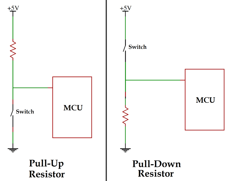
A pull up resistor works by pulling the input pin to a voltage supply with a high logic level when the switch is open. When the switch is closed, it bypasses the pull-up resistor by connecting to ground; thus, the input reads logic LOW.
For pull-down resistors, they pull the input pin to ground, resulting in a LOW logic level when the switch is open. Once the switch is closed, it connects the input pin to a voltage source, thus bypassing the pull-down resistor, making the input read a HIGH logic level.
Basically, the pull-up resistors provide a HIGH logic state as a default while the pull-down resistor provides a LOW logic state by default. Also, they both help prevent cases of floating or undefined input states.
Conclusion
A pull-up resistor remains important in various applications involving digital circuits. This is why they are often included in microcontrollers or added to circuits if the need arises. Always make sure you are using the right pull-up resistor value for the best results. We have also highlighted the best way to troubleshoot such resistors to ensure you get the best performance for an application.
Video: Pull Up Resistor Tutorial
Please send RFQ , we will respond immediately.
Frequently Asked Questions
When should you use a pull-up resistor?
Pull-up resistors come in handy when connecting push-buttons to digital inputs, reading sensor output signals, working with I2C communication lines, and using open-drain or open-collector outputs.
Do you need external pull-up resistors or are the internal ones enough?
It depends on the applications. For some applications, internal pull-ups are enough, while external resistors are needed, especially for precision and high-speed use cases.
Can pull-up resistors work with analog signals?
No. Pull up resistors are only necessary for digital inputs. Using them with analog signals may not help with much but rather lead to distorted voltage levels and inaccurate readings.