What Is an Optocoupler and How Does It Work? The Pro Guide You Need
Author:admin Date: 2026-02-02 08:17 Views:68
Introduction
An optocoupler is an electronic component that transfers electrical signals between two entirely separate circuits using light, without any direct electrical connection. This provides crucial electrical isolation and protects sensitive low-voltage components from surges, high-voltage spikes, and electrical noise.
Construction and Working Mechanism of Optocoupler
The optocoupler functions by leveraging an internal LED and a light-sensitive receiver housed in a single, opaque insulating package. We look at the internal structure and working mechanism below to understand it in detail.
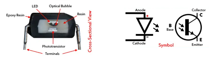
The fundamental structure of the optocoupler centers around an input LED and an output photodetector that is separated by a transparent, insulating gap.
The LED-Photodector Pair
The component comes with two primary sections: the emitter and the detector.
The Emitter is an infrared LED that converts the input electrical current into photons. The Detector is a semiconductor photosensitive device that receives the photons and converts them back into the output electrical current.
Light Emission, Transfer, and Detection Process
Emission: This is when the voltage is applied to the input pins, current flows through the LED.
Transfer: The LED emits infrared light across the internal isolation gap. This gap is made of a clear, electrically insulating material like glass, air, or plastic. This prevents electrical current from passing between the output and input sides.
Detection: Once the light hits the photodetector on the output side, it generates a current in the output circuit proportional to the intensity of the incident light, effectively transferring the signal without electrical contact.
Encapsulation for Insulation and Durability
The entire assembly of the optocoupler is encapsulated in an opaque, ceramic, or durable plastic package. The house is vital for two main reasons, including electrical insulation and environmental protection.
Types of Optocouplers and Their Characteristics
You are likely to encounter a variety of optocoupler types. Below are the common types with their applications.
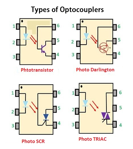
Phototransistor Optocouplers
The phototransistor optocouplers are the most common and fundamental type of opto-isolator in the market. The output stage uses a single bipolar junction phototransistor.
They offer a balance of moderate current transfer ratio, cost-effectiveness, and reasonable switching speeds. The phototransistor works as a standard NPN or PNP transistor, where the base current is replaced by the current generated from incident light.
Common applications: general-purpose signal isolation, microcomputer input/output buffering, and basic DC switching applications.
Photodarlington Optocouplers
These optocouplers use a Darlington transistor pair in the output stage, which essentially connects two transistors in series to multiply the current gain.
It is ideal for applications where the input signal is weak or for driving higher-current loads directly from a low-power source.
Photodiode and Photovoltaic Optocouplers
These types are designed with a focus on either speed or generating an isolated voltage source.
The photodiode optocouplers simply use a photodiode as the detector, while the photovoltaic optocouplers consist of an LED and a stack of photodiodes connected in series.
Electrical and Optical Parameters Explained
Designers rely on various parameters of the optocoupler to ensure the one they choose works out great. Here are important datasheet specifications you need to know:
- Isolation voltage: This is the maximum AC voltage or transient DC voltage that can be applied continuously applied across the isolation barrier without causing a breakdown of the insulation.
- Input forward current: This is the specific current needed to activate the input LED reliably. If you operate outside the recommended range, it impacts performance and lifespan.
- Output collector current or output current: This is the maximum current the output photodetector can safely sink or switch whenever the LED is active.
- Current transfer ratio (CTR): This is the ratio of the output current to the input current. It is usually expressed as a percentage.
- Response time and propagation delay: These define the speed of the device. The response time is the rise and fall time of the output signal. Propagation delay refers to the time lag between the input pulse’s rising/falling edge and the corresponding output pulse’s edge.
Applications of Optocouplers
Optocouplers are used in various industries to provide electrical isolation between circuits, protecting sensitive components and users from high voltages, electrical noise, and surges. Here are some of the examples:
- Power electronics and motor control
- Data communications and logic interfacing
- Medical and safety systems
- Industrial automation and sensing
Optocoupler vs Other Isolation Methods
Optocoupler vs. Transformer
Both optocouplers and transformers provide galvanic isolation, but they use different principles and are suited for different uses.
Transformers use electromagnetic induction through a magnetic field to transfer energy. On the other hand, optocouples use photos or light to transfer the signals across a dielectric barrier.
Transformers excel in terms of efficiently transferring power. For example, converting mains AC voltage to lower voltages to suit an application. Expect the transformers to be larger and heavier, and to typically transfer AC signals that require modulation for DC or low-frequency data.
Optocouplers are designed for signal transfer rather than power transfer. This makes them more compact, lightweight, and they work with both AC and DC signals or data.
So, optocouplers offer superior high-voltage dielectric strength in a small package for signal isolation, while the transformers are best for high power transfer.
Optocoupler vs Digital Isolator
A digital isolator is a new technology that competes directly with an optocoupler in many digital designs. However, they vary in their working principles.
Optocouplers rely on converting electrical signals to light and back to electrical signals. This involves the use of LEDs, photodiodes, or transistors. This process is analog internally.
Digital isolators feature advanced integrated circuits for transmitting digital signals across a physical isolation barrier. They do this by using either high-frequency magnetic fields or changing capacitance coupling. They also transfer digital data directly without the need for analog conversion.
How to Select the Best Optocoupler
Are you looking to choose an optocoupler? Make sure you keep the following parameters in mind to get the right one.
- Define the isolation requirements
This is a critical step for ensuring the device meets the necessary safety standards.
Determine the maximum voltage potential between the input and output circuits. Make sure you select an optocoupler that has an isolation voltage rating that exceeds this maximum voltage by a comfortable margin.
Creepage and clearance are the physical distances that determine how far apart the input and output pins are. Always make sure the package size meets the required safety standards to prevent arcing across the board.
- Determine signal type and speed needs
The signal nature dictates the required internal photodetector.
DC/Digital signals – for slow, general-purpose switching, photodarlington or phototransistors are the best choice.
In the case of high-speed data transmission, make sure to select photodiodes or high-speed digital optocouplers that have specified low propagation delays.
AC signals/power control – for controlling the AC loads, such as motors or lighting, make sure to use photo-SCR or photo-triac optocouplers. Look for models that come with integrated zero-crossing detection to reduce noise.
Analog signals – For linear analog isolation, choose optocouplers designed for linearity. Choose those that come with internal feedback photodiodes.
- Analyze the Current Transfer Ratio (CTR) and load
The CTR helps determine the overall efficiency of signal transfer and the impact of input power requirements.
Start by calculating the required CTR. Start by determining the output current needed to drive a load and the available input current from the source.
Select an optocoupler that has a minimum guaranteed CTR that accommodates your design parameters. If you want long-term reliability, ensure your operating point is within the stable region of the CTR vs input current curve. Also, account for the potential degradation of the LED over time.
We recommend using a photodarlington for high current gain in case the speed is not critical.
- Check the environmental and reliable factors
Check the product’s operating temperature range. Industrial-grade components are best for harsh environments.
Also, power consumption should be considered. Make sure you have the right input current needed by the LED, since optocouplers tend to use more power compared to other modern digital isolators.
Optocoupler Testing Procedure
Testing the optocoupler is key to determining whether it is working correctly and where it is integrated. There are a couple of tests you can perform. They are mostly used to verify whether both the input LED is operating and whether there is a response at the output detector. These tests include:
- Basic functionality test
For this test, you are simply verifying if the internal LED and phototector are working in isolation.
Test the input stage
- Set the multimeter to diode test mode
- Place the red probe on the anode and the black probe on the cathode
- A working LED will display a forward voltage drop. It should be between 1.0 and 1.6V
- Reversing the probes results in an OL or Open Loop reading. This indicates the diode blocks the current flow in reverse.
- If the multimeter shows OL on both tests, the LED is dead.
Test the output stage
The output stage needs the input LED to be energized to conduct current.
Here is how to do it:
- Power the input by applying a safe current to the input LED. This should turn on the LED.
- Measure the output. Start by setting the multimeter to the ohms mode.
- Measure the resistance across the output collector and emitter. A working optocoupler should show very low resistance. Close to zero ohms.
- Turn the input power OFF. When you do this, the resistance across the output immediately becomes very high. It can show OL or megohms, indicating the channel is open.
- If the output resistance remains high regardless of whether there is or no input power, it means the photodetector is likely damaged.
- In-Circuit Functional Testing
You can also get the optocoupler soldered into a circuit board. In this case, an oscilloscope or a multimeter can be used to verify the signal transfer in circuit operation.
- Start by verifying input signal through using an oscilloscope probe. Check that the expected signal is present at the input pins of the optocouplers.
- Verify the output signal as well. Move the oscilloscope probe to the output pins.
- Compare the output signal and the input signal. The output signal is supposed to mirror the input signal, but will have different voltage levels and sometimes be inverted depending on the circuit configuration.
- If a clear, correct signal is present at the input but is now missing or distorted at the output, then it means the optocoupler needs to be replaced.
Conclusion
Optocouplers serve as a bridge between different voltage domains by using light to transfer electrical signals across a non-conductive gap. It provides galvanic isolation to protect sensitive circuitry and users from surges, noise, and spikes. As much as there are other modern digital isolators, the optocouplers remain reliable and cost-effective for many analog and power-control isolation applications.
Please send RFQ , we will respond immediately.
Frequently Asked Questions
Is there a difference between optocouplers and transformers?
As much as both provide isolation, the working principles are different. Optocouplers use light for signal transmission and are best suited for low-power or digital signals. Transformers use magnetic induction, making them suited for AC power or high-current applications.
What is the typical isolation voltage of an optocoupler?
Most optocouplers are designed to offer an isolation voltage ranging from 2.5kV to 5kV. It all depends on their construction and packaging. This also defines how much voltage difference the device will safely withstand between the input and output sides.