
AT24C02 Datenblatt & EEPROM | Arduino
- Marken: Mikrochip-Technologie
- Herunterladen: -
- Preis: Anfrage
- Auf Lager: 25002
- Speichertyp: -
- Speichergröße: -
- Standard: -
- Paket: -


KOSTENLOSE Lieferung für Bestellungen über HK$250.00

Schnelle Reaktion, schnelles Angebot

Blitzversand, keine Sorgen nach dem Verkauf

Originalkanal, Garantie der authentischen Produkte
ROMI2C-B109 | AT24C02 I2C EEPROM memory module
AT24C02
This 2K-bit EEPROM (256 x 8) uses the I²C bus, which makes it super easy to hook up with microcontrollers like Arduino. It runs on a wide voltage range, from 1.7V to 5.5V, so it’s perfect for low-power projects. It’s built to last too, with up to a million write cycles and data retention for up to 40 years. Whether you need to store config settings or log small bits of data, this chip has you covered. It comes in a few package options—8-pin PDIP, SOIC, and TSSOP—so you’ve got flexibility in your design. Plus, the 7-bit address space means you can easily add more devices if you need to.
AT24C02 Pinout and I2C Address
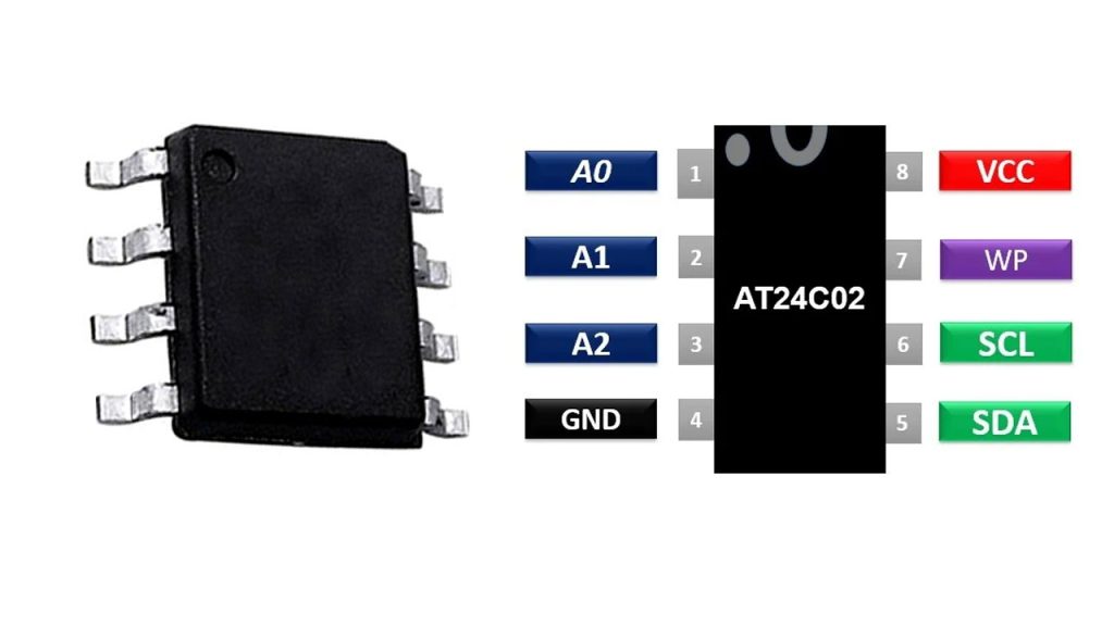
| Stift | Name | Beschreibung |
| 1 | A0 | Address bit 0 (can be tied to GND or VCC) |
| 2 | A1 | Address bit 1 (can be tied to GND or VCC) |
| 3 | A2 | Address bit 2 (can be tied to GND or VCC) |
| 4 | Masse | Ground pin |
| 5 | SDA | Serial Data Line (I²C data line) |
| 6 | SCL | Serial Clock Line (I²C clock line) |
| 7 | WP | Write Protect (can be connected to GND for normal operation) |
| 8 | VCC | Power supply (1.7V to 5.5V) |
For the I²C address, it’s pretty simple. The base address is 0xA0, and you can modify it by setting the A0, A1, and A2 pins. These pins can be connected to either VCC or GND to determine the address, which means you can have up to 8 devices on the same bus, each with a unique address.
Now, the key pins to focus on are SDA (Serial Data Line) and SCL (Serial Clock Line). These are what let you communicate with the AT24C02, so make sure to hook them up to your microcontroller’s corresponding I²C pins.
The A0, A1, A2 pins let you select the device’s address. WP (Write Protect) stops writing to the memory when it’s connected to VCC, so just tie it to GND for regular operation. Lastly, the VCC pin should be powered between 1.7V and 5.5V.
AT24C02 Equivalent EEPROM IC

| Besonderheit | AT24C02 | 24LC02 | M24C02 | CAT24C02 |
| Memory Size | 2 Kbits (256 x 8) | 2 Kbits (256 x 8) | 2 Kbits (256 x 8) | 2 Kbits (256 x 8) |
| Schnittstelle | I²C | I²C | I²C | I²C |
| Spannungsbereich | 1.7V to 5.5V | 1.7V to 5.5V | 2.5V to 5.5V | 1.7V to 5.5V |
| Write Endurance | 1 million cycles | 1 million cycles | 1 million cycles | 1 million cycles |
| Data Retention | 40 years | 40 years | 40 years | 40 years |
| Paketoptionen | 8-pin PDIP, SOIC, TSSOP | 8-pin PDIP, SOIC | 8-pin PDIP, SOIC | 8-pin PDIP, SOIC |
| I²C Address | 0xA0 (Base Address) | 0xA0 (Base Address) | 0xA0 (Base Address) | 0xA0 (Base Address) |
When looking at replacements for the AT24C02, the 24LC02 and CAT24C02 are your go-to options. They share the same 2Kbit memory size and I²C interface, making them perfect substitutes in most applications. These chips also support the same voltage range (1.7V to 5.5V), so you won’t have any issues there.
The M24C02 can also work, but it needs a slightly higher minimum voltage of 2.5V, so be sure to consider that if you’re working with low-voltage systems.
In terms of write endurance and data retention, all of these EEPROMs are pretty similar, offering around 1 million write cycles and 40 years of data retention. So, you don’t need to worry about long-term durability. Just make sure the voltage requirements match your system’s needs.
AT24C02 Arduino Wiring Example

You’ll connect the VCC pin from the EEPROM to the 5V pin on the Arduino and the GND pin to GND. For communication, the SDA pin from the EEPROM goes to the A4 pin on the Arduino, and the SCL pin to A5. To make sure you can write to the EEPROM, just connect the WP (Write Protect) pin to GND to disable write protection. Also, don’t forget to add pull-up resistors (around 4.7kΩ) on both the SDA and SCL lines, connecting them to 5V. This keeps the I²C communication stable and reliable.
The I²C address is set through the A0, A1, and A2 pins. You can connect them to GND or VCC to pick the right address – in most cases, you’ll tie them to GND for the default address, 0xA0.
AT24C02 Memory Read Write Circuit

In this circuit, the AT24C02 EEPROM communicates with a microcontroller through the I²C protocol. You set the I²C address using the A0, A1, and A2 pins by connecting them to VCC or GND. The SDA pin handles data transfer, while the SCL pin keeps the timing in sync. Both SDA and SCL have pull-up resistors (10kΩ) to make sure the signals stay stable, even when no devices are sending data.
The EEPROM is powered through the VCC pin, which connects to 5V or 3.3V, and GND completes the circuit. For normal operation, the HOLD pin is tied to GND, while the CLK pin isn’t used here since the AT24C02 relies on the SCL line for clocking.
This setup allows you to write and read data to the EEPROM by sending the correct address and data, all while keeping things smooth with I²C communication.
AT24C02 Data Logging Circuit Schematic
The AT24C02 EEPROM is perfect for small data storage tasks, like logging sensor data. It has 2 Kbits of memory and uses I²C to communicate with a microcontroller. The address pins (A0, A1, A2) let you set the EEPROM’s address, and you can connect them to VCC or GND to do so. This setup makes it easy to use multiple EEPROMs on the same I²C bus. For communication, the SDA and SCL pins send and receive data, with pull-up resistors (typically 4.7kΩ) keeping the signals stable. If you want to disable writing to the EEPROM, just connect the WP pin to VCC; otherwise, leave it grounded to enable write operations. The microcontroller writes data to the EEPROM by specifying a memory address, and later, it can read the data back when needed, making it great for tasks like logging temperature or sensor readings.
AT24C02 Raspberry Pi Connection Guide
When you connect the AT24C02 EEPROM to a Raspberry Pi, you’ll use the I²C protocol to handle communication. The VCC pin goes to 3.3V or 5V on the Pi, depending on your EEPROM’s requirements, while GND connects to the Pi’s ground. For data transfer, connect the SDA pin to GPIO 2 (SDA) and the SCL pin to GPIO 3 (SCL) on the Pi. These pins manage the data and clock signals for I²C. To enable writing to the EEPROM, make sure the WP (Write Protect) pin is connected to GND; if you connect it to VCC, the EEPROM will be read-only. The A0, A1, and A2 pins help set the EEPROM’s I²C address, typically defaulting to 0x50 when connected to GND. You’ll also need pull-up resistors (4.7kΩ) on the SDA and SCL lines to stabilize the communication. Once everything’s set up, you can easily read and write data from the EEPROM with Python.
Ähnliche Artikel

ZXCW6100S28
Diodes Incorporated

TDA8541T/N1,112
NXP USA Inc.

TDA8541T/N1,118
NXP USA Inc.

TDA7056B/N1,112
NXP USA Inc.
,SOT157-2.JPG "TDA2616Q/N1,112")
TDA2616Q/N1,112
NXP USA Inc.

TDA8547TS/N1,112
NXP USA Inc.
TDA8547TS/N1,118
NXP USA Inc.

NE58633BS,157
NXP USA Inc.
NE58633BS,115
NXP USA Inc.

SA58670BS,115
NXP USA Inc.

TS4961TIQT
STMicroelectronics
,SOT523-1.JPG "TFA9842J/N1,112")
TFA9842J/N1,112
NXP USA Inc.
Auch in den Warenkorb legen
PCA9674ATS,112
NXP USA Inc.

SN74V225-20PAG
Texas Instruments

ATTINY13A-SUR
Mikrochip-Technologie

LTC4059AEDC#TRMPBF
Analog Devices Inc.

SI2404-C-GTR
Skyworks Solutions Inc.

TL064CD
STMicroelectronics

EP22V10ELC-15
Altera

MS51PC0AE
Nuvoton Technology Corporation

PIC16F876A-I/SO
Mikrochip-Technologie

LT1763CDE-3.3#PBF
Analog Devices Inc.

LC4256V-5T144C
Lattice Semiconductor Corporation

SI2141-B10-GMR
Skyworks Solutions Inc.
Verwandte Produkte
ZXCW6100S28
Diodes Incorporated
TDA8541T/N1,112
NXP USA Inc.
TDA8541T/N1,118
NXP USA Inc.
TDA7056B/N1,112
NXP USA Inc.
TDA2616Q/N1,112
NXP USA Inc.
TDA8547TS/N1,112
NXP USA Inc.
TDA8547TS/N1,118
NXP USA Inc.
NE58633BS,157
NXP USA Inc.
NE58633BS,115
NXP USA Inc.
SA58670BS,115
NXP USA Inc.
TS4961TIQT
STMicroelectronics
TFA9842J/N1,112
NXP USA Inc.

SA58632BS,118
NXP USA Inc.

TDA1308TT/N2,118
NXP USA Inc.
TDA8552TS/N1,112
NXP USA Inc.
TDA8552TS/N1,118
NXP USA Inc.
TDA1517/N3,112
NXP USA Inc.
TDA7056A/N2,112
NXP USA Inc.

SA58671UK,027
NXP USA Inc.

TDA8948J/N1,112
NXP USA Inc.
TFA9843AJ/N1,112
NXP USA Inc.

SA58637BS,118
NXP USA Inc.

TDA7052A/N2,112
NXP USA Inc.

TDA8551T/N1,112
NXP USA Inc.

TDA8551T/N1,118
NXP USA Inc.
SA58672UK,027
NXP USA Inc.
SA58670ABS,115
NXP USA Inc.

SA58631TK,157
NXP USA Inc.
SA58631TK,118
NXP USA Inc.
SA58631TK,115
NXP USA Inc.
Bitte senden Sie eine RFQ, wir werden umgehend antworten.
