
IRF840 | Datasheet, Circuit Diagram, Pinout, Equivalent Motorola
- FET-Typ: N-Kanal
- Drain-Source-Spannung (Vdss): 500 V
- Strom-Dauerentnahme (Id) bei 25 °C: 8A (Tc)
- Paket: TO-220AB


KOSTENLOSE Lieferung für Bestellungen über HK$250.00

Schnelle Reaktion, schnelles Angebot

Blitzversand, keine Sorgen nach dem Verkauf

Originalkanal, Garantie der authentischen Produkte
IRF840 MOSFET Complete Details | Working Principle and Best 5 Equivalent MOSFETs | IRF840 Advantages
IRF840 Pinout
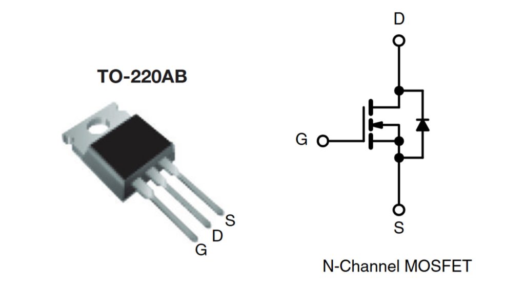
The IRF840 is a high-voltage N-channel MOSFET commonly packaged in a TO-220AB case. It is widely used in power supplies, motor control, and inverter circuits due to its fast switching performance and high breakdown voltage. Understanding the correct pin configuration is essential for proper circuit integration and to avoid device failure.
| PIN-Nummer | Pin-Name | Beschreibung |
|---|---|---|
| 1 | Tor (G) | Controls the MOSFET. A voltage applied here turns the device on or off. |
| 2 | Abfluss (D) | Main current flows through this terminal when the MOSFET is turned on. |
| 3 | Quelle (S) | Connected to ground or the low-side of the circuit. It completes the circuit path. |
Accurate identification of the IRF840’s Gate, Drain, and Source pins ensures optimal performance and safe operation in high-voltage applications. Always consult the datasheet for maximum ratings and thermal management considerations when designing with this MOSFET.
IRF840 Circuit
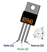
irf840 Pinout Diagram
Die irf840 ist eine N-Kanal-MOS-Feldeffektröhre im TO-220-Gehäuse. Die Hauptmerkmale sind niedrige Gate-Ladung, geringe Rückkopplungskapazität und sehr schnelles Schalten. Daher wird sie in den meisten Fällen als Schaltröhre eingesetzt, beispielsweise bei hocheffizienten DC-DC-Schaltungen (bei denen durch Schalten mit unterschiedlichen Frequenzen unterschiedliche Gleichspannungen ausgegeben werden können).
The use of irf840 in circuit design should be noted that: almost all of the mos tube in the circuit design, need to drive the circuit, the direct use of microcontroller or DSP output control signals are mostly not up to the MOS tube required to drive the voltage or current, so the need for driver circuit. Driver circuit is generally divided into current-driven and voltage-driven according to the MOS is current-controlled or voltage-controlled to choose the type of driver circuit. Specifically as shown in the following two diagrams:
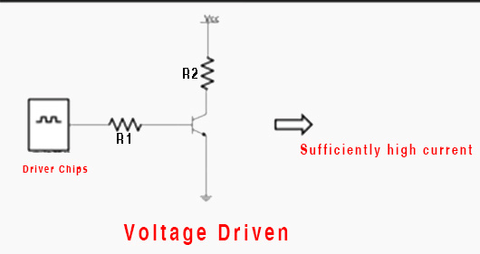
Current Control Picture
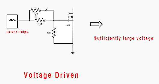
Voltage Control Picture
Ähnliche Artikel
~~3.jpg "IRFU9024NPBF")
IRFU9024NPBF
International Rectifier

FDG6335N
onsemi

MMBFJ201
onsemi

IRF3205PBF
International Rectifier

IRFP1405PBF
International Rectifier

IRF3205ZSTRLPBF
International Rectifier

IRFP4229PBF
International Rectifier

IRFB7437PBF
International Rectifier
.jpg "IRLR9343TRPBF")
IRLR9343TRPBF
International Rectifier
IRFP4468PBF
International Rectifier
IRF640NSTRLPBF
International Rectifier

FDS6375
National Semiconductor
Auch in den Warenkorb legen

BVSS138LT1G
onsemi

IRF7401TRPBF
Infineon Technologies

NDT3055
Fairchild Semiconductor
IRFZ48NPBF
Infineon Technologies

AOD4189
Alpha & Omega Semiconductor Inc.

IRF7404TRPBF
International Rectifier

IRFML8244TRPBF
Infineon Technologies
;;2.jpg "STD3N95K5AG")
STD3N95K5AG
STMicroelectronics

STF10NM60N
STMicroelectronics

IRF200S234
International Rectifier
FDS6630A
onsemi

NTR4170NT1G
onsemi
Verwandte Produkte
IRFU9024NPBF
International Rectifier
FDG6335N
onsemi
MMBFJ201
onsemi
IRF3205PBF
International Rectifier
IRFP1405PBF
International Rectifier
IRF3205ZSTRLPBF
International Rectifier
IRFP4229PBF
International Rectifier
IRFB7437PBF
International Rectifier
IRLR9343TRPBF
International Rectifier
IRFP4468PBF
International Rectifier
IRF640NSTRLPBF
International Rectifier
FDS6375
National Semiconductor
IRFB4332PBF
International Rectifier

IRFP3306PBF
International Rectifier

NVTFS5811NLTAG
onsemi
NVTFS4823NTWG
onsemi

NVD5117PLT4G
onsemi
IRF200S234
Infineon Technologies
.jpg "IRF840PBF")
IRF840PBF
Infineon Technologies

AO4407
Alpha & Omega Semiconductor Inc.

2SK3377-Z-E1-AZ
Renesas Electronics America Inc

NVD5867NLT4G
onsemi

NVMFS5A160PLZWFT1G
onsemi

FDWS9510L-F085
onsemi
FDWS9509L-F085
onsemi
NVTFS5826NLWFTAG
onsemi

AON7401L
Alpha & Omega Semiconductor Inc.
AO4407AL
Alpha & Omega Semiconductor Inc.

AO3407
Alpha & Omega Semiconductor Inc.

CPH3461-TL-W
onsemi
Bitte senden Sie eine RFQ, wir werden umgehend antworten.
