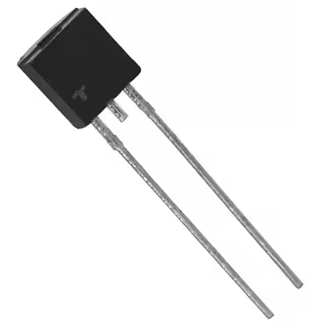
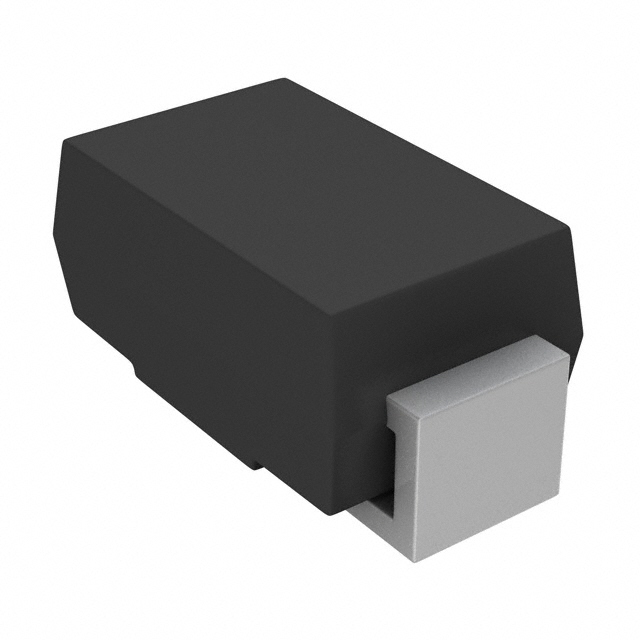
S-1-4 Datenblatt, Preis, PDF
- Marken: Eaton - Bussmann Electrical Division
- Herunterladen: -
- Preis: Anfrage
- Auf Lager: 29,337
- Zubehörtyp: -
- Paket: Schüttgut

KOSTENLOSE Lieferung für Bestellungen über HK$250.00

Schnelle Reaktion, schnelles Angebot

Blitzversand, keine Sorgen nach dem Verkauf

Originalkanal, Garantie der authentischen Produkte
Key Features of the S-1-4
The S-1-4 is a versatile, low-dropout (LDO) voltage regulator designed to provide stable output voltage with minimal power loss. It is ideal for battery-powered applications, offering efficient power regulation in compact and energy-conscious designs. With an input voltage range that accommodates various power sources, the S-1-4 ensures a reliable and consistent 3.3V or 5V output. This LDO is known for its low quiescent current, making it perfect for devices that require low standby power consumption. Whether you’re working on IoT projects, portable electronics, or power management systems, the S-1-4 delivers the performance and efficiency needed to optimize your circuit.
S-1-4 Pinout
| PIN-Nummer | Pin-Name | Beschreibung |
|---|---|---|
| 1 | IN | Input pin. Connect to the input power source, typically 5V or 3.3V. |
| 2 | Masse | Ground pin. Connect to the system ground for proper operation. |
| 3 | AUS | Output pin. Provides the regulated output voltage, typically 3.3V or 5V. |
| 4 | ON/OFF | Enable pin. Used to turn the regulator on or off. Connect to a control signal for power management. |
Pinout Usage and Notes
The S-1-4 voltage regulator has four pins: IN, GND, OUT, and ON/OFF. The IN pin is where you connect the input voltage source, while the OUT pin provides the regulated output voltage. Make sure the input voltage is within the specified range to ensure stable operation. The GND pin is used to connect the system ground, which is critical for proper functioning. The ON/OFF pin allows you to control the regulator’s operation by either enabling or disabling it with a logic signal. This feature is useful for power management in battery-operated devices. Always ensure proper connections to avoid damaging the regulator.
S-1-4 Equivalent Models
| Modell | Input Voltage | Ausgangsspannung | Ausgangsstrom | Ruhestrom | Pakettyp | Anwendung |
|---|---|---|---|---|---|---|
| S-1-4 | 2.0V to 6.0V | 3,3 V / 5 V | 150 mA | 30µA | SOT-23-5 | Power management, portable devices |
| LD1117-3.3 | 3.0V to 15V | 3,3 V | 800 mA | 5 mA | SOT-223 | Battery-powered devices, low-power systems |
| AMS1117-3.3 | 3.0V to 15V | 3,3 V | 800 mA | 5 mA | SOT-223 | Consumer electronics, power supply systems |
| TPS7A02 | 1.4V to 6.5V | 3,3 V | 200 mA | 30µA | SOT-23-5 | Low-noise, precision power regulation |
Equivalent Models Usage and Notes
If you’re considering alternatives to the S-1-4, models like the LD1117-3.3 and AMS1117-3.3 are good options, offering similar output voltage and current capabilities. However, these models are slightly less efficient, with higher quiescent current compared to the S-1-4. The TPS7A02 is a great high-precision alternative if you require very low-noise power regulation, though it has a lower output current limit. When choosing an equivalent, ensure that the input voltage range and output current are suitable for your application, and consider whether you need features like low-noise performance or higher efficiency.
Choosing the Right Voltage Regulator for Your Project
When selecting a voltage regulator like the S-1-4, it’s important to consider factors like output voltage, current rating, and quiescent current. If you’re looking for something with higher current handling, the LD1117-3.3 or AMS1117-3.3 might be better choices, but they come with slightly higher quiescent current. For low-noise and precise voltage regulation, the TPS7A02 is an excellent option, though it has a lower current limit. Make sure the regulator you choose matches your project’s power requirements, whether you need a compact, low-power solution like the S-1-4 or something with higher current handling for larger systems.
I couldn’t locate a specific schematic featuring the S-1-4 voltage regulator. However, I can provide a general overview of how to use an LDO voltage regulator like the S-1-4 in a circuit.
Typical LDO Voltage Regulator Circuit
In a standard setup, the LDO regulator is connected as follows:
-
Input Pin (IN): Connects to the input voltage source, typically 5V or 3.3V.
-
Ground Pin (GND): Connects to the common ground of the circuit.
-
Output Pin (OUT): Provides the regulated output voltage, such as 3.3V or 5V, depending on the regulator’s specifications.
-
Enable Pin (ON/OFF): Controls the activation of the regulator. A high signal (e.g., 3.3V) enables the regulator, while a low signal (e.g., 0V) disables it.
Additionally, capacitors are often placed at the input and output to stabilize the voltage and reduce noise. For instance, a 10µF ceramic capacitor might be used at the input, and a 10µF tantalum capacitor at the output.
Circuit Analysis
-
Power Supply: Ensure the input voltage is within the specified range for the regulator. For the S-1-4, this typically ranges from 2.0V to 6.0V.
-
Capacitors: Use recommended capacitor types and values to maintain stability and minimize noise. Refer to the regulator’s datasheet for specific recommendations.
-
Enable Pin: Properly manage the enable pin to control the regulator’s operation. Leaving it floating can lead to unpredictable behavior.
For detailed information and specific application circuits, it’s advisable to consult the datasheet of the S-1-4 voltage regulator. This document provides comprehensive guidelines on capacitor selection, layout considerations, and typical application circuits to ensure optimal performance.


