SN74HC138N datasheet, pinout, pdf | Arduino
- Type: Decoder/Demultiplexer
- Circuit: 1 x 3:8
- Independent Circuits: 1
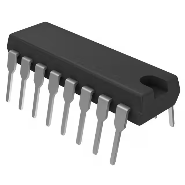
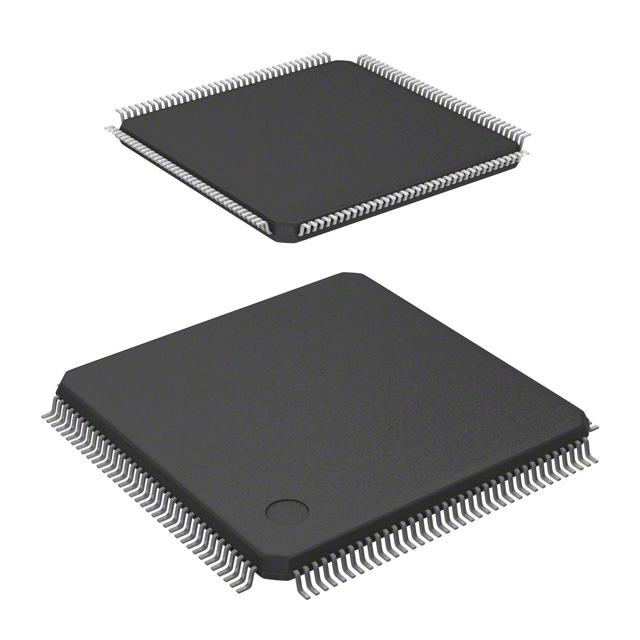
- Package: 16-DIP (0.300, 7.62mm)

FREE delivery for orders over HK$250.00

Quick response, quick quotaton

Flash shipment,no worries after sales

Original channel,guarantee of the authentic products
SN74HC244N Octal Buffer
SN74HC138N
If you’re working with decoders or need a quick way to select one of eight output lines based on three binary inputs, the SN74HC138N is a solid choice. This high-speed 3-to-8 line decoder/demultiplexer from Texas Instruments offers minimal delay, making it perfect for fast operations. It’s part of the HC family, so you can expect low power consumption, which is great for projects where energy efficiency matters. Plus, it works with both active-high and active-low logic inputs, giving you flexibility in your designs. It also has a wide supply voltage range from 2V to 6V, and with two enable pins, you can control the output state precisely. Simple, reliable, and efficient—this chip fits right into your next project.
SN74HC138N Pinout Configuration

| Pin Number | Pin Name | Function |
|---|---|---|
| 1 | A0 | Input (Least Significant Bit) |
| 2 | A1 | Input |
| 3 | A2 | Input |
| 4 | G1 | Active Low Enable Input |
| 5 | G2 | Active Low Enable Input |
| 6 | G3 | Active Low Enable Input |
| 7 | Y0 | Output |
| 8 | Y1 | Output |
| 9 | Y2 | Output |
| 10 | Y3 | Output |
| 11 | Y4 | Output |
| 12 | Y5 | Output |
| 13 | Y6 | Output |
| 14 | Y7 | Output |
| 15 | Vcc | Power Supply (Positive) |
| 16 | GND | Ground |
A0, A1, and A2 are the address pins that pick which of the eight outputs (Y0 to Y7) will be activated. Basically, the combo of these pins decides which output gets turned on. G1, G2, and G3 are the enable pins, and all three need to be low for the decoder to work. If any of them are high, the outputs won’t be active. Y0 to Y7 are the output lines, and one of them will be activated (low) based on the address inputs and enable pin settings.
A couple of things to remember: Keep the enable pins low to make sure the outputs are active, and connect A0, A1, and A2 to a stable signal to avoid glitches. Also, make sure Vcc and GND are hooked up right for everything to run smoothly.
SN74HC138N Equivalent Decoder IC

| Parameter | SN74HC138N | 74LS138 | 74HCT138 | 74AC138 | 74ACT138 |
|---|---|---|---|---|---|
| Package Type | PDIP-16 | PDIP-16 | PDIP-16 | PDIP-16 | PDIP-16 |
| Voltage Range (V) | 4.5V to 5.5V | 4.75V to 5.25V | 4.5V to 5.5V | 4.5V to 5.5V | 4.5V to 5.5V |
| Output Type | Active Low | Active Low | Active Low | Active Low | Active Low |
| Logic Levels | TTL Compatible | TTL Compatible | CMOS Compatible | CMOS Compatible | CMOS Compatible |
| Max Propagation Delay (ns) | 35 ns | 35 ns | 25 ns | 14 ns | 9 ns |
| Enable Inputs | 3 | 3 | 3 | 3 | 3 |
| Notes | Standard 3-to-8 decoder with enable | Low power, similar logic levels | Faster propagation delay | High-speed alternative | Faster and more power-efficient |
When choosing between different models, the voltage range is something to keep in mind. The 74LS138 has a narrower range than some others, which might limit compatibility in some setups. For applications where speed is crucial, the 74ACT138 is your best bet, with a super fast 9 ns delay. If you’re looking for a good balance between speed and delay, the 74AC138 with its 14 ns delay works well. Another thing to consider is logic compatibility: the SN74HC138N uses TTL logic, while the 74HCT138 and 74AC138 are CMOS-compatible, which means better power efficiency and speed. And if low power consumption is a priority, the 74HCT138 and 74ACT138 are the ones to go for.
SN74HC138N Decoder Circuit Example

The SER pin on the SN74HC595B gets serial data, one bit at a time. Each time you send a pulse to SRCLK, the data shifts in. Once all the bits are in, a pulse on RCLK locks that data into the output pins like Qa, Qb, and so on.
These outputs (Qa, Qb, etc.) are connected to the address lines (A, B, C) of the SN74HC138N decoder. Depending on what values are at A, B, and C, the decoder picks one of the outputs (Y0 to Y7) and pulls it low, while keeping the others high.
When an output is pulled low, it can power up devices like LEDs. For example, when the output is low, current flows through the connected LED, lighting it up. The diodes in the circuit help prevent damage from reverse current.
This setup lets you control a bunch of outputs without using too many microcontroller pins. It’s a great way to save space and still manage multiple devices.
SN74HC138N Arduino Interface Wiring
To set things up, start by connecting the VCC (pin 16) of the SN74HC138N to 5V on your Arduino and GND (pin 8) to GND on the Arduino. Then, hook up the address pins (A, B, and C) to three digital pins on the Arduino, like pins 2, 3, and 4. These pins will decide which output (Y0-Y7) gets activated.
Next, connect the enable pins (G1, G2, G3) to GND to activate the outputs. If any of these are connected to HIGH, the outputs won’t work.
Finally, wire the decoder outputs (Y0-Y7) to the components you want to control, such as LEDs. Use a current-limiting resistor (220Ω or 330Ω) in series with each LED to prevent too much current. For example, connect Y0 to an LED, then connect the LED’s anode to 5V and cathode to Y0 through the resistor. Repeat this for the other outputs.
SN74HC138N Binary to Decimal Decoder Circuit

The SN74HC138N is a 3-to-8 line decoder, which means it takes 3 bits of input and decodes them into one of 8 outputs, corresponding to the numbers 0 through 7. In this circuit, the inputs ADDR0, ADDR1, ADDR2, and ADDR3 control which of the 8 outputs (Y0-Y7) will be active, turning on the connected LEDs. The address inputs (ADDR0 – ADDR3) provide the binary code that selects the output to activate. For example, if the binary input is 001, it will turn on LED1 (Y1). The enable lines (ENLD, E1, E2, E3) control whether the outputs are active. If any of these lines are high, the decoder won’t output anything. The Y0 – Y7 outputs are connected to the LEDs, and only one LED will be lit at a time, depending on the address input.
SN74HC138N LED Display Driver Application
If you’re working with a multi-digit 7-segment display, the SN74HC138N is a great way to simplify things. It decodes a 3-bit binary input into one of 8 outputs, each controlling one digit of the display. You can select which digit to light up using the address lines (ADDR0-ADDR2) and then control the segments (A-G) based on the desired number. By controlling the enable lines, you can manage which digits are active.
To show numbers, the digits are multiplexed—switched on and off rapidly—so it seems like all digits are lit at once. The SN74HC138N helps select the active digit during this process. Using this setup reduces the number of pins needed on the microcontroller, making it easy to scale for more digits.
