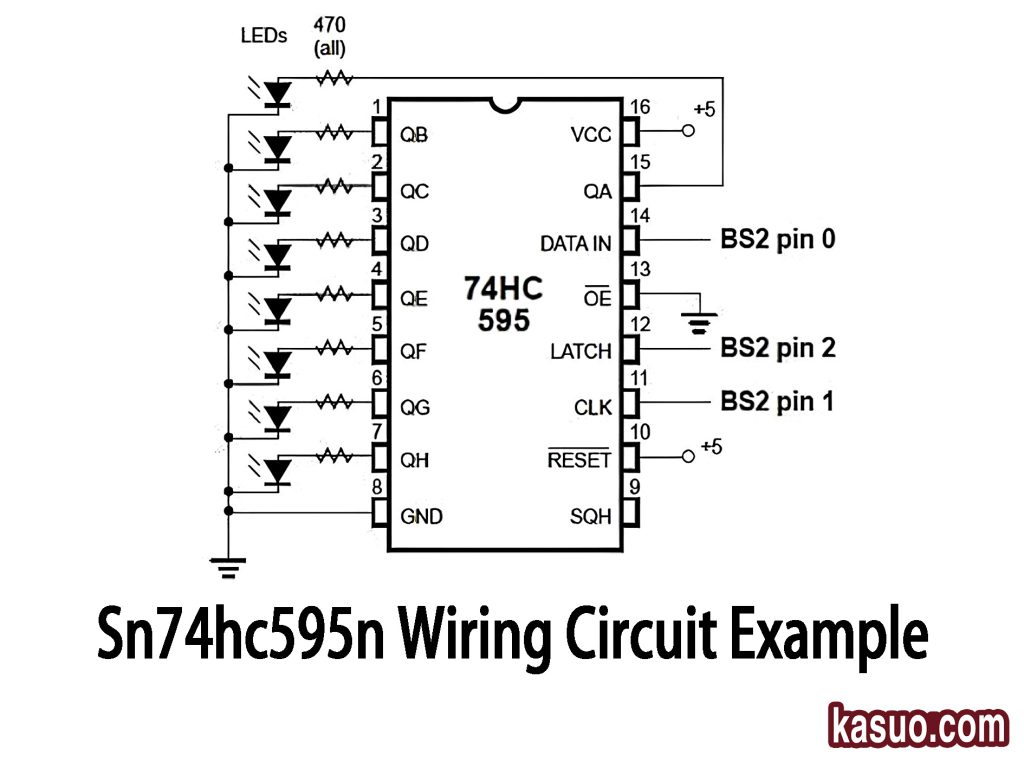
This circuit uses a 74HC595 shift register to control 8 LEDs. Here’s how it works: First, connect VCC to 5V and GND to ground. The LEDs are connected to the output pins QA to QH (pins 15-7) through current-limiting resistors (around 470Ω) to protect them. The DATA IN pin (pin 14) gets the serial data input, usually from a microcontroller. The CLK pin (pin 11) shifts the data, and the LATCH pin (pin 12) locks it into place. Finally, OE (pin 13) enables the outputs, allowing the LEDs to turn on/off based on the data. This setup is great for controlling multiple LEDs with minimal pins from your microcontroller.

SN74HC595N datasheet, LED pinout, shift register
Discover the SN74HC595N Reference Manual for comprehensive details on pinout, shift register, and circuit designs. Whether you're working with Arduino, Raspberry Pi, or planning a new project, this guide offers essential information. Perfect for those needing a tutorial or exploring uses in various applications.
- Logic Type: Shift Register
- Output Type: Tri-State
- Number of Elements: 1
- Package: 16-DIP (0.300, 7.62mm)


FREE delivery for orders over HK$250.00

Quick response, quick quotaton

Flash shipment,no worries after sales

Original channel,guarantee of the authentic products
Sn74hc595n
If you’re working on an Arduino or microcontroller project and running out of GPIO pins, the SN74HC595N chip from Texas Instruments is your best friend. It’s a handy 8-bit shift register, letting you expand from just 3 GPIO pins to control 8 outputs easily.
What’s great about this chip is the built-in latch function—it keeps your outputs stable without flickering. Need more outputs? No problem; just chain multiple chips together for even more expansion.
Operating between 2V and 6V (usually 5V), it’s flexible enough for most applications and uses very little power, making it ideal for battery-powered projects. Each pin can handle about 6mA, perfect for driving LEDs (don’t forget current-limiting resistors!).
You’ll often see this chip controlling LED displays, 7-segment screens, LCD interfaces, or extra outputs for home and industrial electronics. Its low cost, easy setup, and reliability make it popular in electronics prototyping and embedded systems.
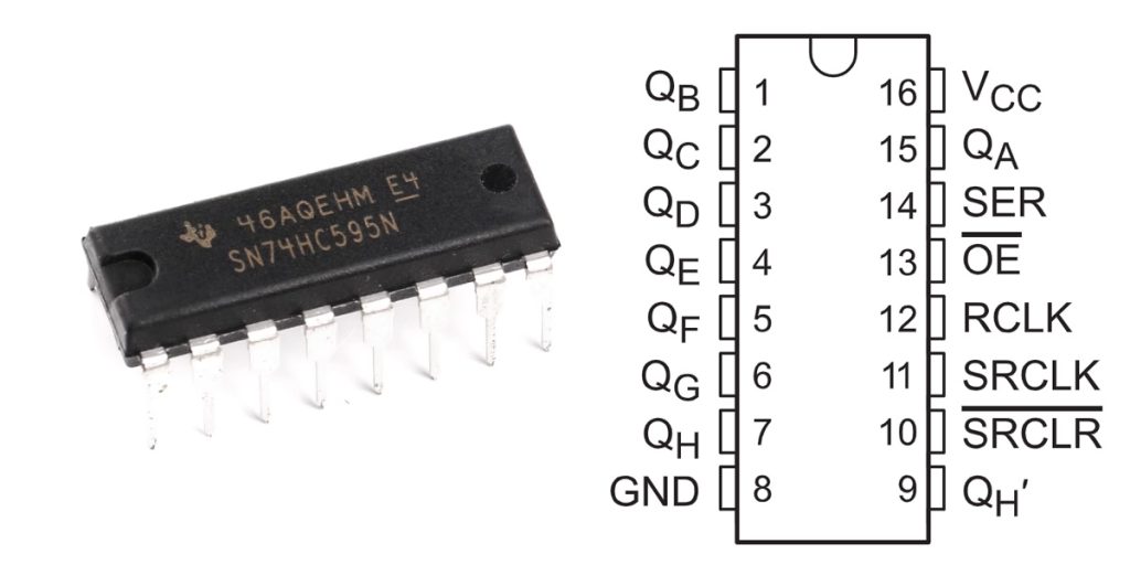
Sn74hc595n Pinout
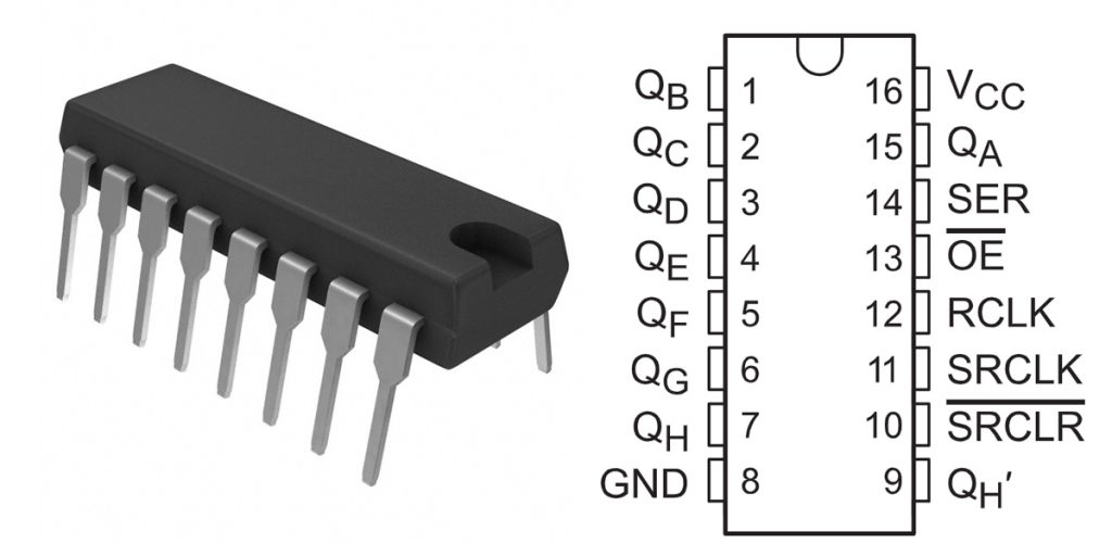
| Pin Number | Pin Name | Function Description |
|---|---|---|
| 1 | Qb | Parallel output, output pin B |
| 2 | Qc | Parallel output, output pin C |
| 3 | Qd | Parallel output, output pin D |
| 4 | Qe | Parallel output, output pin E |
| 5 | Qf | Parallel output, output pin F |
| 6 | Qg | Parallel output, output pin G |
| 7 | Qh | Parallel output, output pin H |
| 8 | GND | Ground (0V) |
| 9 | Qh’ (Qh_bar) | Serial data output, cascades to next 595 chip |
| 10 | SRCLR | Shift register clear input (active low) |
| 11 | SRCLK | Shift register clock input (rising-edge triggered) |
| 12 | RCLK | Storage register clock input (rising-edge triggered) |
| 13 | OE | Output enable (active low) |
| 14 | SER | Serial data input |
| 15 | Qa | Parallel output, output pin A |
| 16 | VCC | Positive power input (typically 5V) |
When wiring up the SN74HC595N, here’s how you handle the pins clearly and safely. Your data goes into the SER pin (pin 14), and every time SRCLK (pin 11) detects a rising edge, it shifts that data into the internal register. But remember, the outputs only update when RCLK (pin 12) sees a rising edge, so that’s how you prevent output glitches.
Always tie OE (pin 13) to ground to enable outputs; if you lift it high, the chip turns off outputs completely. The SRCLR pin (pin 10) usually stays connected to 5V, but briefly pulling it low clears all data instantly.
To link multiple chips together, use the Qh’ pin (pin 9) as the data source for the next chip’s SER input. Finally, always ensure the chip’s powered correctly (5V to VCC and proper grounding). And if your loads draw more than about 6mA per pin, add transistors or MOSFETs to handle that extra current safely.
Sn74hc595n Equivalent


| Parameter \ Model | SN74HC595N (TI) | 74LS595 (TI) | MC74HC595AN (ON Semi) | CD4094BE (TI) |
|---|---|---|---|---|
| Package Type | DIP-16 | DIP-16 | DIP-16 | DIP-16 |
| Supply Voltage (VCC) | 2V ~ 6V | 4.75V ~ 5.25V | 2V ~ 6V | 3V ~ 15V |
| Operating Speed (Max) | 25 MHz (5V) | 25 MHz | 25 MHz (5V) | ~5 MHz |
| Output Drive Current | ±6mA | ±8mA | ±6mA | ±6.8mA |
| Logic Type | CMOS | TTL | CMOS | CMOS |
| Power Consumption | Low | Higher | Low | Very Low |
| Output Type | Parallel Latched Output | Parallel Latched Output | Parallel Latched Output | Parallel Latched Output |
| Output Enable Function | Yes | Yes | Yes | Yes |
| Clear Pin | Yes | Yes | Yes | No (Latch Control Only) |
| Replacement Compatibility | – | Higher | Very High | Moderate |
If you’re thinking about swapping your SN74HC595N chip, here are a few things to keep in mind.
The 74LS595 is TTL-based, meaning it draws a bit more power and strictly requires a stable 5V supply—so probably not your best bet if battery life matters. But it does handle slightly higher currents per output pin, making it good for driving more LEDs.
A simpler, safer swap is the MC74HC595AN, essentially identical to your original SN74HC595N. Just double-check availability, especially since it’s made by ON Semi.
Finally, there’s the CD4094BE. It has a wider voltage range (3-15V) but is slower (around 5MHz). It also lacks a dedicated clear-pin, so check carefully if it fits your circuit needs.
Whichever you choose, always double-check voltage ratings, pin compatibility, speed, and logic levels before making the switch to ensure everything works smoothly.
Sn74hc595n Wiring Circuit Example
Sn74hc595n Arduino Led Control

This circuit is a great example of how to use an Arduino UNO to control a 74HC595 shift register and drive 8 LEDs. Here’s how it works:
First, you’ll connect the SER pin to one of Arduino’s digital pins to send data, and the SRCLK pin to another Arduino pin to control when data shifts in. Then, the RCLK pin will sync the output, sending the data from the shift register to the output pins (Qa to Qh) when the clock pulses.
For power, connect VCC and GND of the 74HC595 to 5V and ground on the Arduino. Each of the 8 output pins will be connected to an LED through a current-limiting resistor, with all LEDs’ negative terminals tied to ground.
The Arduino sends 8-bit data through the shift register, controlling the LEDs. You can create cool effects like chasers or running lights by changing the data sent.
Just remember to use appropriate resistors to prevent damaging your LEDs and ensure each output pin can handle up to 6-8mA. If you need more LEDs, you can cascade another 74HC595 by connecting the Qh’ pin to the next SER pin. This simple setup is a great way to get hands-on with serial communication and I/O expansion.
Sn74hc595n Vs 74hc595
| Parameter | SN74HC595N | 74HC595 |
|---|---|---|
| Package Type | DIP-16, SOIC-16 | DIP-16, SOIC-16 |
| Logic Family | CMOS | TTL |
| Voltage Supply | 2V to 6V | 4.5V to 5.5V |
| Max Clock Frequency | 100 MHz | 25 MHz |
| Output Drive Current | ±6mA | ±6mA |
| Operating Temperature | -40°C to +85°C | 0°C to +70°C |
| Power Consumption | Low (CMOS technology) | Higher (TTL technology) |
| Applications | Suitable for low-power, battery-operated devices | Suitable for high-speed applications but with more power consumption |
When you’re choosing between the SN74HC595N and the 74HC595, the key difference is power consumption. The SN74HC595N is CMOS-based, meaning it uses less power and has a wider voltage range (2V to 6V), making it a good choice for battery-powered projects. On the other hand, the 74HC595 is TTL-based, so it’s a bit faster (higher clock frequency) but uses more power and works within a narrower voltage range (4.5V to 5.5V). If you’re swapping one for the other, make sure the voltage and power fit your project needs, especially if you’re working on low-power or battery-driven systems.
Sn74hc595n 7 Segment Display Project
Here’s how the SN74HC595N shift register works to control a 7-segment display. You’ll start by sending serial data through the DATA IN pin, which tells the register which segments to light up on the display. The CLK (clock) pin helps move the data through the register, shifting it one bit at a time with each clock pulse. Once the data is in, the LATCH pin locks it in place, and the outputs (QA-QH) control the segments (A-G) of the display.
To set it up, connect DATA IN to an Arduino digital pin (like D2), CLK and LATCH to other pins (D3 and D4), and then connect the register’s outputs to the 7-segment display. Don’t forget to add a current-limiting resistor (around 220Ω or 470Ω) for each LED segment to avoid damage.
In your code, you’ll map each number (0-9) to its corresponding binary pattern for the display, and then use shiftOut() to send the data and update the display. You can even create more complex displays like counting or a timer!
Sn74hc595n Shift Register Tutorial
If you’re working with microcontrollers like Arduino and you’re running low on GPIO pins, the SN74HC595N shift register is a lifesaver. Basically, this chip lets you turn just a few pins into many outputs, perfect for controlling LEDs or displays.
Here’s how it works: You feed your data serially into the chip through the DATA IN pin. Then, using the CLOCK pin, you shift this data bit by bit. Once all your data’s in, you activate the LATCH pin, and all your outputs update simultaneously. Easy, right?
You get 8 extra output pins (QA to QH) per chip, and you can even link several chips together if you need more outputs. Plus, it uses very little power and works anywhere from 2V to 6V, ideal for battery-powered projects.
You’ll often see this chip controlling 7-segment displays, LED patterns, or relays. It’s a simple yet powerful solution for expanding your project’s capabilities.
Sn74hc595n Daisy Chain Connection
If you need to control a lot of outputs but are running low on microcontroller pins, daisy-chaining SN74HC595N shift registers is a great solution. In a daisy-chain setup, you connect the DATA OUT (QH) of one shift register to the DATA IN (SER) of the next. The CLOCK and LATCH pins are shared across all the shift registers.
Here’s how it works: Data flows from one shift register to the next, bit by bit. With each clock pulse, the data shifts through the registers. When you use the LATCH pin, all the shift registers update at once, so all outputs change together.
This setup saves pins because you only need one DATA IN, CLOCK, and LATCH line, no matter how many shift registers you add. It’s perfect for controlling lots of LEDs, driving larger displays, or even automating systems with motors or relays.
Sn74hc595n Clock Latch Explanation
When working with the SN74HC595N shift register, there are two important pins you’ll use to control how data flows: Clock (SHCP) and Latch (STCP).
-
Clock (SHCP) Pin: This pin tells the shift register when to move the data. Each time the clock gets a pulse, it shifts the data bit by bit from the DATA IN pin into the register. If you’re using multiple shift registers in a chain, the clock pulses also move the data along from one register to the next.
-
Latch (STCP) Pin: After the data is shifted into the register, it doesn’t show up on the output pins (QA-QH) until you pulse the latch pin. This makes the data visible on the output pins, which can then control things like LEDs or relays.
To sum it up: The Clock moves data into the register, and the Latch makes it appear on the output pins. Together, they let you control multiple devices using just a few pins on your microcontroller.
Sn74hc595n Gpio Expansion
When you’re working on microcontroller projects, you’ll often run out of GPIO pins quickly. The SN74HC595N shift register is a handy way around this—it lets you control multiple devices, like LEDs, motors, or relays, using just three microcontroller pins.
Here’s how it works: you send your data bit-by-bit into the shift register through the DATA IN pin. Each clock pulse shifts the data forward inside the chip. When all your bits are in place, you trigger the latch pin, which updates the outputs (QA-QH) all at once.
With one SN74HC595N, you can control eight outputs from just three microcontroller pins. Need more outputs? No problem. You can chain several registers together easily—the data flows through each chip sequentially, expanding your outputs even more. This setup simplifies your wiring and saves GPIO pins, making your project cleaner and easier to manage.
More Like This

XC9237A09DMR-G
Torex Semiconductor Ltd
XC9237A0LDMR-G
Torex Semiconductor Ltd
XC9237A08DMR-G
Torex Semiconductor Ltd

XC9236E11CER-G
Torex Semiconductor Ltd
XC9236E1ACER-G
Torex Semiconductor Ltd
XC9236E10CER-G
Torex Semiconductor Ltd
XC9236E0MCER-G
Torex Semiconductor Ltd
XC9236E09CER-G
Torex Semiconductor Ltd
XC9236E0LCER-G
Torex Semiconductor Ltd
XC9236E08CER-G
Torex Semiconductor Ltd
XC9236D08DER-G
Torex Semiconductor Ltd
XC9236C40D4R-G
Torex Semiconductor Ltd
Also Add to Cart
DS90UH929TRGCRQ1
Texas Instruments

SN74ACT1073NSR
Texas Instruments

8N4DV85LC-0012CDI8
Renesas Electronics America Inc

ADG3304WBRUZ-REEL
Analog Devices Inc.

100LVEL11MX
onsemi
XC6806B35011-G
Torex Semiconductor Ltd

MP9840GL-P
Monolithic Power Systems Inc.

74HC4049DB,112
Nexperia USA Inc.

LM337T
onsemi
MAX712EPE+
Analog Devices Inc./Maxim Integrated

LP5907MFX-1.8/NOPB
Texas Instruments

OPA3832ID
Texas Instruments
Related Products
XC9237A09DMR-G
Torex Semiconductor Ltd
XC9237A0LDMR-G
Torex Semiconductor Ltd
XC9237A08DMR-G
Torex Semiconductor Ltd
XC9236E11CER-G
Torex Semiconductor Ltd
XC9236E1ACER-G
Torex Semiconductor Ltd
XC9236E10CER-G
Torex Semiconductor Ltd
XC9236E0MCER-G
Torex Semiconductor Ltd
XC9236E09CER-G
Torex Semiconductor Ltd
XC9236E0LCER-G
Torex Semiconductor Ltd
XC9236E08CER-G
Torex Semiconductor Ltd
XC9236D08DER-G
Torex Semiconductor Ltd
XC9236C40D4R-G
Torex Semiconductor Ltd
XC9236C3MD4R-G
Torex Semiconductor Ltd
XC9236C39D4R-G
Torex Semiconductor Ltd
XC9236C3LD4R-G
Torex Semiconductor Ltd
XC9236C38D4R-G
Torex Semiconductor Ltd
XC9236C3KD4R-G
Torex Semiconductor Ltd
XC9236C37D4R-G
Torex Semiconductor Ltd
XC9236C3HD4R-G
Torex Semiconductor Ltd
XC9236C36D4R-G
Torex Semiconductor Ltd
XC9236C3FD4R-G
Torex Semiconductor Ltd
XC9236C35D4R-G
Torex Semiconductor Ltd
XC9236C3ED4R-G
Torex Semiconductor Ltd
XC9236C34D4R-G
Torex Semiconductor Ltd
XC9236C3DD4R-G
Torex Semiconductor Ltd
XC9236C33D4R-G
Torex Semiconductor Ltd
XC9236C3CD4R-G
Torex Semiconductor Ltd
XC9236C32D4R-G
Torex Semiconductor Ltd
XC9236C3BD4R-G
Torex Semiconductor Ltd
XC9236C31D4R-G
Torex Semiconductor Ltd
Please send RFQ , we will respond immediately.

Please send RFQ , we will respond immediately.
Copyright © 2024 All Rights Reserved