
STM32F407VGT6 datasheet, discovery board & reference manual
- CoreProcessor: ARM® Cortex®-M4
- Core Size: 32-Bit Single-Core
- Peripherals: Brown-out Detect/Reset, DMA, I²S, LCD, POR, PWM, WDT
- Package: 100-LQFP


FREE delivery for orders over HK$250.00

Quick response, quick quotaton

Flash shipment,no worries after sales

Original channel,guarantee of the authentic products
STM32F407VGT6 Supplier and ST STM32F407VGT6 Distributor in China – Rantle East Electronic
STM32F407VGT6
The STM32F407VGT6 is a very popular 32-bit microcontroller featuring a high-performance Arm Cortex-M4 core running at speeds up to 168 MHz. It’s powerful, stable, and more than capable of handling typical complex tasks. With ample storage—1MB of Flash memory and 192KB of SRAM—it meets the requirements of most embedded development projects. Moreover, this MCU offers a rich set of interfaces including USB, Ethernet, CAN, SPI, and UART, making common functionalities readily accessible. It’s especially suitable for industrial control systems, smart home devices, and various IoT applications.
STM32F407VGT6 pinout diagram
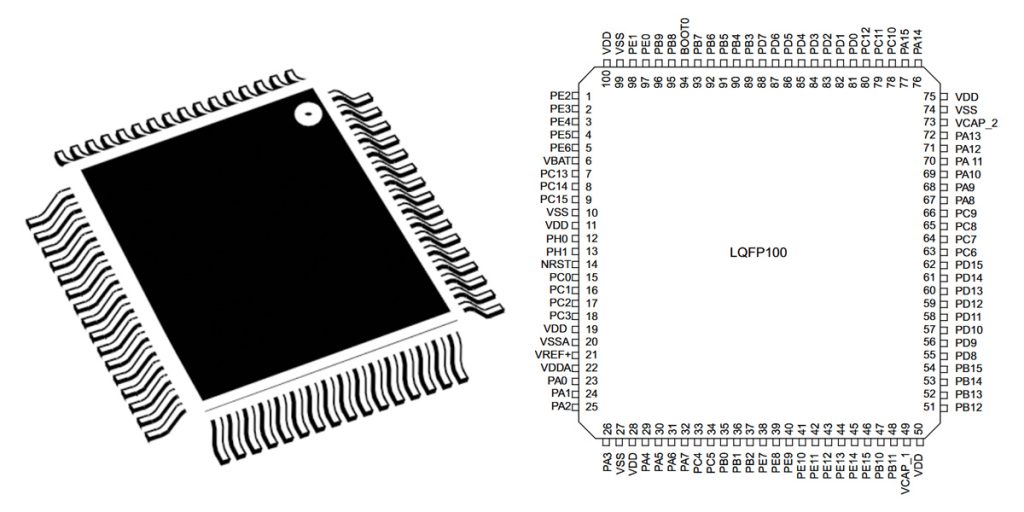
| Pin No. | Pin Name | Default Function | Example Alternate Functions | Description |
|---|---|---|---|---|
| 1 | VBAT | Power | – | Backup battery input |
| 2 | PC13 | GPIO | RTC_AF1 | General-purpose input/output |
| 3 | PC14 | GPIO | OSC32_IN | 32kHz oscillator input |
| 4 | PC15 | GPIO | OSC32_OUT | 32kHz oscillator output |
| 5 | PH0 | GPIO | OSC_IN | External oscillator input |
| 6 | PH1 | GPIO | OSC_OUT | External oscillator output |
| 7 | NRST | Reset | – | Reset input |
| 8 | PC0 | GPIO | ADC123_IN10 | General-purpose input/output |
| 9 | PC1 | GPIO | ADC123_IN11 | General-purpose input/output |
| 10 | PC2 | GPIO | ADC123_IN12 | General-purpose input/output |
| 11 | PC3 | GPIO | ADC123_IN13 | General-purpose input/output |
| 12 | VSSA | Ground | – | Analog ground |
| 13 | VREF+ | Power | – | Analog reference voltage |
| 14 | PA0 | GPIO | ADC123_IN0 | General-purpose input/output |
| 15 | PA1 | GPIO | ADC123_IN1 | General-purpose input/output |
| 16 | PA2 | GPIO | ADC123_IN2 | General-purpose input/output |
| 17 | PA3 | GPIO | ADC123_IN3 | General-purpose input/output |
| 18 | VSSA | Ground | – | Analog ground |
| 19 | VREF+ | Power | – | Analog reference voltage |
| 20 | PA4 | GPIO | ADC123_IN4 | General-purpose input/output |
| 21 | PA5 | GPIO | ADC123_IN5 | General-purpose input/output |
| 22 | PA6 | GPIO | ADC123_IN6 | General-purpose input/output |
| 23 | PA7 | GPIO | ADC123_IN7 | General-purpose input/output |
| 24 | PC4 | GPIO | ADC12_IN14 | General-purpose input/output |
| 25 | PC5 | GPIO | ADC12_IN15 | General-purpose input/output |
| 26 | PB0 | GPIO | ADC12_IN8 | General-purpose input/output |
| 27 | PB1 | GPIO | ADC12_IN9 | General-purpose input/output |
| 28 | PB2 | GPIO | BOOT1 | General-purpose input/output |
| 29 | PB10 | GPIO | I2C2_SCL | General-purpose input/output |
| 30 | PB11 | GPIO | I2C2_SDA | General-purpose input/output |
| 31 | VCAP_1 | Capacitor | – | Internal regulator output |
| 32 | VSS | Ground | – | Digital ground |
| 33 | VDD | Power | – | Digital power supply |
| 34 | PB12 | GPIO | SPI2_NSS | General-purpose input/output |
| 35 | PB13 | GPIO | SPI2_SCK | General-purpose input/output |
| 36 | PB14 | GPIO | SPI2_MISO | General-purpose input/output |
| 37 | PB15 | GPIO | SPI2_MOSI | General-purpose input/output |
| 38 | PD8 | GPIO | USART3_TX | General-purpose input/output |
| 39 | PD9 | GPIO | USART3_RX | General-purpose input/output |
| 40 | PD10 | GPIO | USART3_CK | General-purpose input/output |
| 41 | PD11 | GPIO | USART3_CTS | General-purpose input/output |
| 42 | PD12 | GPIO | TIM4_CH1 | General-purpose input/output |
| 43 | PD13 | GPIO | TIM4_CH2 | General-purpose input/output |
| 44 | PD14 | GPIO | TIM4_CH3 | General-purpose input/output |
| 45 | PD15 | GPIO | TIM4_CH4 | General-purpose input/output |
| 46 | PC6 | GPIO | TIM3_CH1 | General-purpose input/output |
| 47 | PC7 | GPIO | TIM3_CH2 | General-purpose input/output |
| 48 | PC8 | GPIO | TIM3_CH3 | General-purpose input/output |
| 49 | PC9 | GPIO | TIM3_CH4 | General-purpose input/output |
| 50 | PA8 | GPIO | MCO1 | General-purpose input/output |
Note: Only selected pins and functions are shown here. For complete pin definitions and alternate functionalities, please refer to the official STM32F407VGT6 datasheet.
STM32F407VGT6 compatible stm32 chips
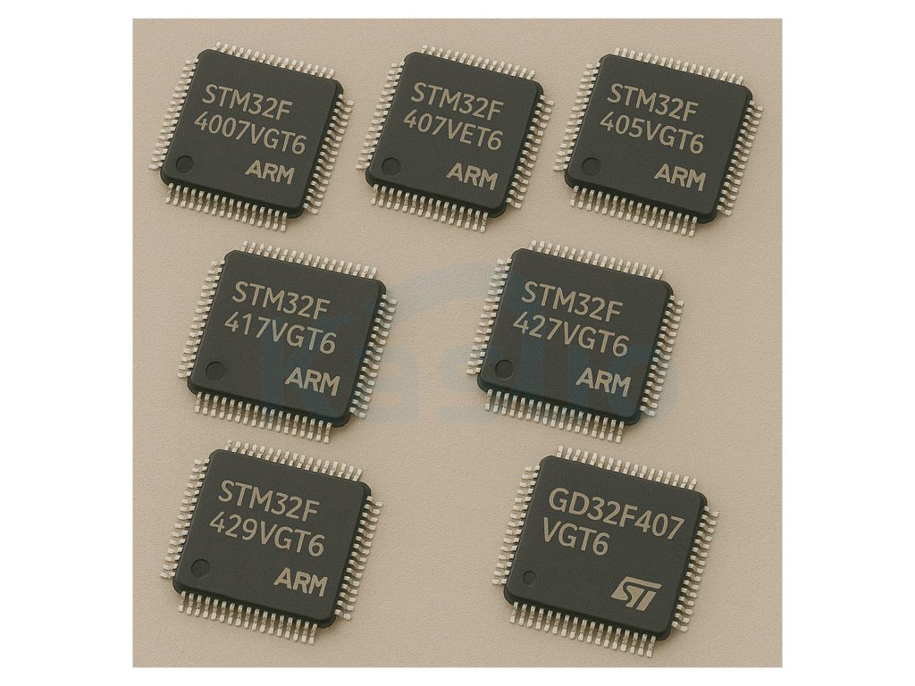
| Model | Core | Flash (KB) | RAM (KB) | Max Freq (MHz) | Ethernet | USB OTG | Crypto | Notes |
|---|---|---|---|---|---|---|---|---|
| STM32F407VGT6 | Cortex-M4 | 1024 | 192 | 168 | Yes | Yes | No | Baseline model |
| STM32F407VET6 | Cortex-M4 | 512 | 192 | 168 | Yes | Yes | No | Lower flash size; same peripherals |
| STM32F405VGT6 | Cortex-M4 | 1024 | 192 | 168 | No | Yes | No | No Ethernet; otherwise similar |
| STM32F417VGT6 | Cortex-M4 | 1024 | 192 | 168 | Yes | Yes | Yes | Adds hardware crypto support |
| STM32F427VGT6 | Cortex-M4 | 1024 | 256 | 180 | Yes | Yes | Yes | Higher performance; more RAM |
| STM32F429VGT6 | Cortex-M4 | 1024 | 256 | 180 | Yes | Yes | Yes | Adds TFT LCD controller |
| GD32F407VGT6 | Cortex-M4 | 1024 | 192 | 168 | Yes | Yes | No | GigaDevice clone; not binary compatible with STM32F407VGT6 |
When selecting a replacement for the STM32F407VGT6, ensure that the alternative microcontroller matches your application’s requirements in terms of peripherals, memory size, and performance. While some models like the STM32F407VET6 offer lower flash memory, others like the STM32F427VGT6 provide enhanced performance and additional features. Be cautious with clones like the GD32F407VGT6, as they may not be fully compatible with STM32 firmware and development tools.
STM32F407VGT6 wiring schematic example
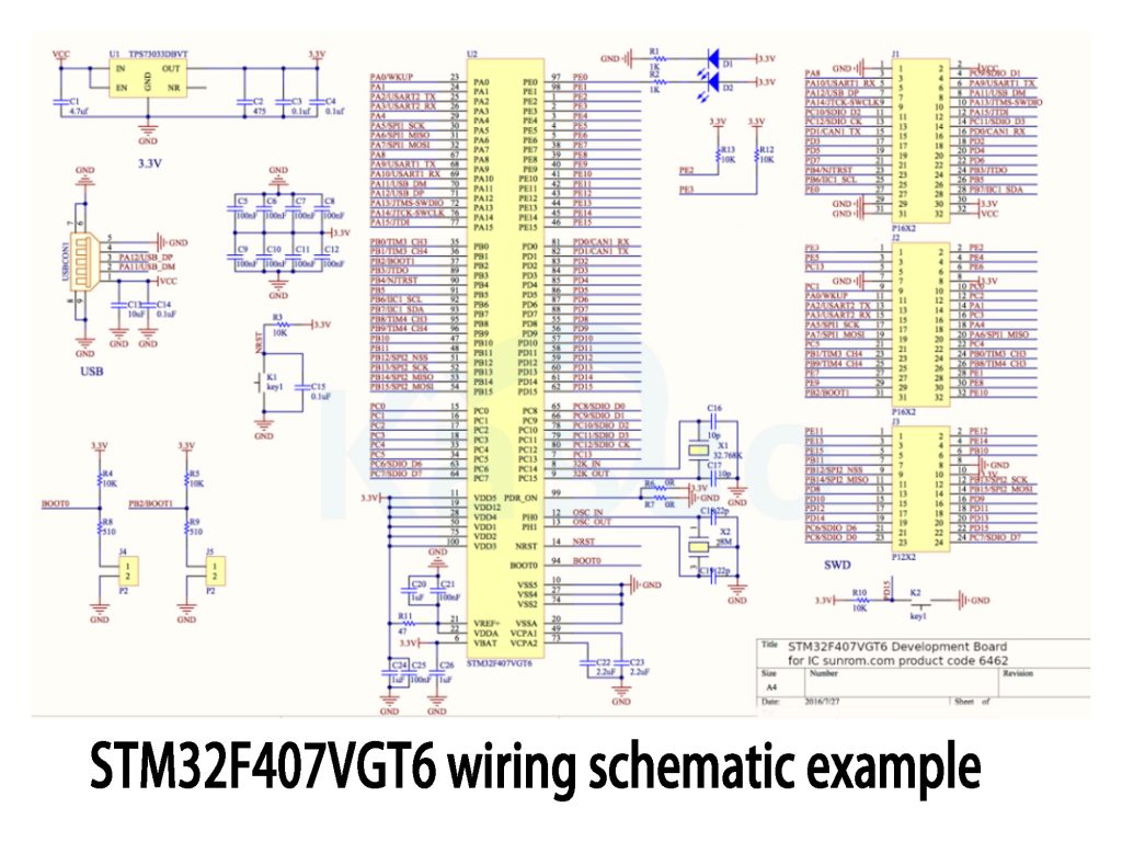
In the middle, highlighted in yellow, is the main microcontroller of this board, the STM32F407VGT6. It’s a 32-bit ARM Cortex-M4 MCU with plenty of GPIO pins, UART (serial), SPI, and I²C interfaces, making it really easy to connect sensors and various peripherals.
Looking over to the left side, you can see the power supply circuit featuring the AMS1117-3.3 voltage regulator. This regulator takes in a 5V input (for example, from a USB port) and converts it down to a stable 3.3V to power the MCU. You’ll notice several capacitors placed next to it—these help smooth out voltage fluctuations. A lot of unexpected issues with development boards can be traced back to poor power design, so these capacitors are genuinely important.
The crystal oscillator circuit on the board is another key area. The primary oscillator is an 8MHz crystal, essentially acting as the “heartbeat” of the board—stability here is crucial to ensure proper program execution. Nearby, there’s also a small 32.768kHz crystal for the real-time clock (RTC), allowing precise timing while maintaining low power consumption.
The board also includes a dedicated JTAG/SWD debug interface (the 20-pin connector you see), making it easy to program or debug the MCU. Next to it, you’ll find the serial communication circuit, enabling easy connectivity with computers or other external devices.
Overall, this schematic is very practical—it covers all essential functions clearly without becoming overly complex. Its clean layout makes it a great choice for developing embedded projects based on the STM32F407VGT6.
STM32F407VGT6 vs stm32f103 performance
STM32F407VGT6 and STM32F103 are both popular STM32 microcontrollers, but the F407 is notably more advanced. The STM32F407VGT6 features an ARM Cortex-M4 core running at 168MHz, offering significantly higher computational performance, DSP capabilities, and a floating-point unit (FPU). In contrast, the STM32F103 uses a simpler ARM Cortex-M3 core at 72MHz, without DSP or FPU, thus suitable for simpler or less computationally intensive tasks. Additionally, the STM32F407 provides more peripheral interfaces, larger memory (up to 1MB Flash), and enhanced real-time performance, making it ideal for high-performance applications like complex embedded systems and industrial automation.
STM32F407VGT6 application in motor control
The STM32F407VGT6 is a high-performance 32-bit microcontroller widely used in motor control applications. With its fast 168MHz ARM Cortex-M4 core, high-precision ADC modules, and extensive PWM outputs, it can precisely manage motor speed, torque, and positioning. Additionally, it supports various communication interfaces (such as CAN and USART), allowing for easy implementation of complex multi-axis motor synchronization. It’s particularly suitable for industrial automation, robotics control, electric vehicle drives, and other demanding applications.
More Like This

MC5430F
Motorola

JD54LS51BCA
National Semiconductor

USPLSI2032VE-110LB49
Lattice Semiconductor Corporation
74S22PC
Rochester Electronics, LLC

9504DC
National Semiconductor

9005PC
National Semiconductor

9007DC
National Semiconductor
9004DC
National Semiconductor

SN74HC804DWR
Texas Instruments
SN700863DWR
Texas Instruments
4001BDMQB
National Semiconductor
54F02FMQB
National Semiconductor
Also Add to Cart

MX25L6433FM2Q-09G
Macronix

MIC2358YLQ
Microchip Technology

MC74AC161D
onsemi
1SX280HN1F43I2VG
Intel

MC14513BCPG
onsemi

74AHC164PW,112
Nexperia USA Inc.

CP2104-MINIEK
Silicon Labs

74HC4024D,652
NXP Semiconductors

SN74S124N3
Texas Instruments

PIC16F1579-E/GZ
Microchip Technology

DP83822IRHBR
Texas Instruments

TPS5420MDREP
Texas Instruments
Related Products
MC5430F
Motorola
JD54LS51BCA
National Semiconductor
USPLSI2032VE-110LB49
Lattice Semiconductor Corporation
74S22PC
Rochester Electronics, LLC
9504DC
National Semiconductor
9005PC
National Semiconductor
9007DC
National Semiconductor
9004DC
National Semiconductor
SN74HC804DWR
Texas Instruments
SN700863DWR
Texas Instruments
4001BDMQB
National Semiconductor
54F02FMQB
National Semiconductor
DM54S20W/883
National Semiconductor
MC3129L
Motorola
4071BDM
National Semiconductor
MC9814P
Motorola
MC9825P
Motorola

74AC11000NS
Texas Instruments
MC5420L
Motorola
MC5401L
Motorola
MC5401F
Motorola
SN74H61N
Texas Instruments
MC5410F
Motorola
MC5430L
Motorola

SN74AS138N-J
Texas Instruments
CD4023BCN
Fairchild Semiconductor
4019BDC
National Semiconductor
74H40DC
National Semiconductor
5420FMQB
National Semiconductor
4025BDM
National Semiconductor
Please send RFQ , we will respond immediately.
