
XPT2046 digipi with esphome
- Marcas: XPT (Tecnología XPTEK de Shenzhen)
- Descargar: -
- Precio: consulta
- En stock: 22534
- Interfaz: -
- Temperatura de funcionamiento: -
- Resolution (Bits): -
- Paquete: TSSOP-16


Envío GRATUITO para pedidos superiores a HK$250.00

Respuesta rápida, cotización rápida.

Envío rápido, sin preocupaciones posventa.

Canal original, garantía de los productos auténticos.
XPT2046 – Touch Screen Driver
xpt2046
If you’re looking into using the XPT2046 chip for your project, it’s a great pick for resistive touchscreen applications—like industrial machines, consumer gadgets, or embedded systems. Setting it up is pretty straightforward because it uses an SPI interface that can run up to 2MHz, keeping communication simple and fast.
What’s really nice is its accuracy; it features a 12-bit analog-to-digital converter, so you’ll get precise touch positions without hassle. Plus, it works well across a wide power range (2.2V to 5.25V), making it versatile for different setups, especially battery-powered ones since it consumes only about 260µA.
Also, don’t worry about extreme environments—this chip can handle temperatures from -40°C to 85°C. It’s small too, usually packaged as a compact TSSOP-16, easy to integrate even if your space is limited. So, overall, it’s reliable, efficient, and perfect if you want something robust and easy to use.
Xpt2046 Pinout
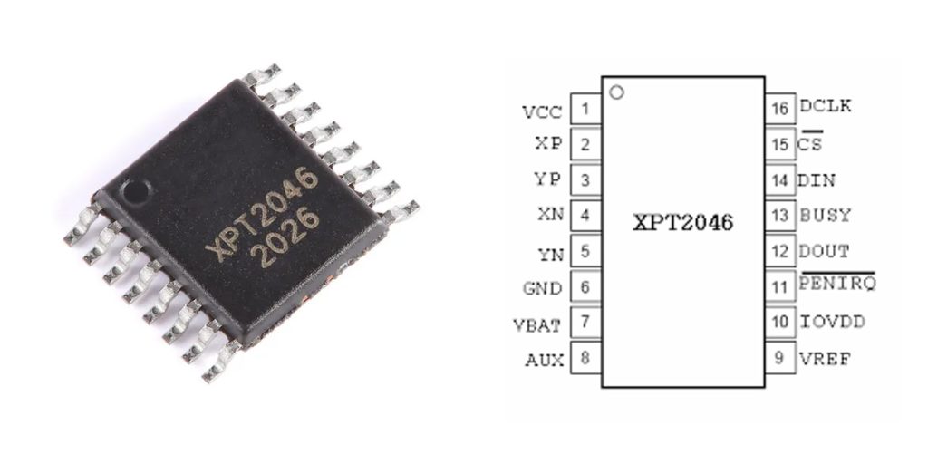
| Número PIN | Nombre del pin | Description (Connection to TFT LCD Touchscreen) |
|---|---|---|
| 1 | VCC | Power Supply Voltage (Typically 3.3V) |
| 2 | XP | Touchscreen X+ Electrode |
| 3 | YP | Touchscreen Y+ Electrode |
| 4 | XN | Touchscreen X- Electrode |
| 5 | YN | Touchscreen Y- Electrode |
| 6 | VBAT | Battery Monitoring (Typically not used; can float) |
| 7 | AUX | Auxiliary Analog Input (Typically unused) |
| 8 | VREF | ADC Reference Voltage (Usually tied to VCC) |
| 9 | Tierra | Suelo |
| 10 | PENIRQ | Touch Interrupt Signal, Active Low |
| 11 | DOUT | SPI Data Output (MISO) |
| 12 | BUSY | Busy Status Output (Can float if unused) |
| 13 | DIN | SPI Data Input (MOSI) |
| 14 | CS | SPI Chip Select (Active Low) |
| 15 | CLK | SPI Clock Input |
| 16 | VCC | Power Supply (Internally connected to pin 1) |
When you’re wiring up the XPT2046 touch controller, there are a few tips that’ll help things go smoothly. First, it’s designed for standard SPI communication, meaning you’ll connect four main wires: CLK for clock, DIN for data-in (MOSI), DOUT for data-out (MISO), and CS as your chip-select, which activates at low voltage.
Next, connecting your touchscreen correctly is crucial. The XP, XN, YP, and YN pins need to go to the corresponding electrodes on your TFT LCD’s resistive touchscreen. Usually, it goes like this: XP to X+, XN to X-, YP to Y+, and YN to Y-. Be careful here—mixing these up will definitely cause weird touch responses or misreadings.
Also, the PENIRQ pin is handy; it signals your MCU whenever the screen is touched. Hook it to an interrupt pin on your microcontroller for quick touch detection.
Connect the VREF pin directly to your VCC to maintain accurate ADC readings. And for any unused pins, like VBAT, AUX, or BUSY, just leave them floating to avoid interference. Lastly, adding a small 0.1µF capacitor near the chip’s power pin helps keep things stable.
Xpt2046 Equivalent Touch Controller
| Parameter \ Model | XPT2046 | TSC2046 (TI) | ADS7843 (TI) | HR2046 |
|---|---|---|---|---|
| Tipo de paquete | TSSOP-16 | TSSOP-16 | TSSOP-16 | TSSOP-16 |
| Communication Interface | SPI | SPI | SPI | SPI |
| ADC Resolution | 12 bits | 12 bits | 12 bits | 12 bits |
| Voltaje de operación | 2.2~5.25V | 2.2~5.25V | 2.7~5.25V | 2.2~5.25V |
| Max SPI Speed | ~2MHz | ~2MHz | ~2MHz | ~2MHz |
| Operating Temperature Range | -40°C~85°C | -40°C~85°C | -40°C~85°C | -40°C~85°C |
| Typical Power Consumption | 260µA | 280µA | 300µA | 260µA |
| Interrupt Output | Yes (PENIRQ) | Yes (PENIRQ) | Yes (PENIRQ) | Yes (PENIRQ) |
| Pin Compatibility | – | Fully Compatible | Fully Compatible | Fully Compatible |
If you’re looking for alternatives to the XPT2046, there are a couple of great options you can consider. The TSC2046 and ADS7843 from Texas Instruments (TI) are both solid choices and completely pin-compatible with the XPT2046. This means you can swap them directly without worrying about redesigning your board. Just keep in mind that the ADS7843 needs a minimum of 2.7V to operate, slightly higher than XPT2046’s 2.2V.
Another option, especially if you’re cost-conscious, is the HR2046—a Chinese-made chip with similar specs, interface, and pin arrangement. It offers excellent value for the money, but since brand and supply stability might vary, it’s wise to thoroughly test some samples first before going all-in.
Overall, focus on matching the voltage range, SPI interface, ADC resolution, and package type. TI chips like TSC2046 and ADS7843 provide long-term reliability, while cheaper alternatives like the HR2046 require extra validation to ensure consistent performance in your projects.
Xpt2046 Spi Wiring With Arduino
| XPT2046 Pin | Arduino UNO Pin | Descripción |
|---|---|---|
| VCC (1,16) | 3.3V or 5V | Power Supply (Typically 3.3V) |
| GND (9) | Tierra | Common Ground |
| CS (14) | D10 | SPI Chip Select Signal |
| DIN (13) | D11 (MOSI) | SPI Data Input |
| DOUT (11) | D12 (MISO) | SPI Data Output |
| CLK (15) | D13 (SCK) | SPI Clock |
| PENIRQ (10) | D2 or another interrupt pin | Touch Interrupt Input (Optional) |
| BUSY (12) | Floating | Busy Status Output (Typically unused) |
| XP, XN, YP, YN | Connected to touchscreen electrodes | Touchscreen electrode connections |
| VREF (8) | VCC (3.3V or 5V) | ADC Reference Voltage |
| VBAT (6), AUX (7) | Floating | Unused pins, can float |
When you’re setting up your XPT2046 with an Arduino UNO, there are a few important tips that’ll save you headaches later. First off, always use a 3.3V supply—this protects your touchscreen and improves measurement stability, especially when paired with a TFT LCD.
For SPI connections, stick to the standard Arduino pins: MOSI to pin D11, MISO to D12, and SCK to D13. You’ll typically connect the CS pin to digital pin 10, but you can choose a different pin if needed.
Also, pay close attention to wiring the touchscreen electrodes—make sure XP/XN and YP/YN match correctly with your four-wire touchscreen. Any mistakes here, and your touchscreen will respond inaccurately or not at all.
To quickly detect touches, connect the PENIRQ pin (active-low interrupt) to an external interrupt pin on the Arduino, like D2 or D3.
Lastly, the BUSY pin isn’t typically used, so you can leave it floating without worrying. Following these tips ensures your setup will run smoothly and reliably.
Xpt2046 Touch Interface Circuit
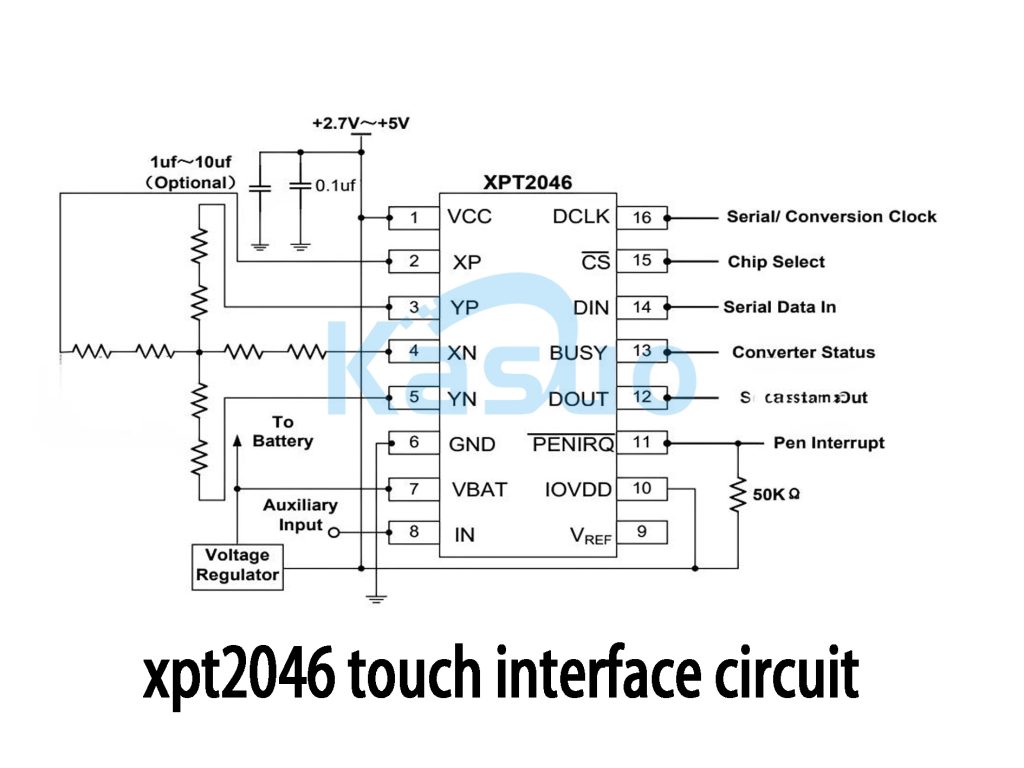
If you’re building a resistive touchscreen circuit with the XPT2046, let me break down how it works in a way that’s easy to follow. The XPT2046 handles reading your touchscreen’s signals and converting them into digital coordinates that your microcontroller can understand through SPI.
You’ll wire XP, XN, YP, and YN directly to your touchscreen. These measure voltage changes when the screen is touched, pinpointing the exact position. SPI communication uses standard pins—DCLK for timing, CS to select the chip (active-low), DIN to receive commands from your MCU, and DOUT to send data back.
When the screen gets pressed, the PENIRQ pin drops to a low signal, alerting your MCU through an interrupt. Your MCU then sends an SPI command, prompting the chip to convert the touch position into digital data you can use.
Make sure you add a 0.1µF ceramic capacitor plus a 1-10µF electrolytic capacitor to keep your power supply stable. Also, leave unused pins like AUX or VBAT floating to avoid noise. It’s a solid, reliable design suitable for industrial gear, consumer gadgets, or portable devices.
Xpt2046 Vs Ads7846 Difference
| Parámetro | XPT2046 | ADS7846 |
|---|---|---|
| Chip Type | Resistive Touchscreen Controller | Resistive Touchscreen Controller |
| ADC Resolution | 12 bits | 12 bits |
| Interface Type | SPI | SPI |
| Rango de voltaje de operación | 2.2V ~ 5.25V | 2,7 V ~ 5,25 V |
| Operating Current (Typical) | 260 µA | 750 µA |
| Operating Temperature Range | -40°C ~ 85°C | -40°C ~ 85°C |
| Max SPI Clock Frequency | ~2 MHz | ~2 MHz |
| Tipo de paquete | TSSOP-16 | TSSOP-16 |
| Pin Compatibility | Fully Compatible | Fully Compatible |
| PENIRQ Interrupt Function | Sí | Sí |
| Fabricante | XPT (Domestic Brand) | Texas Instruments (TI) |
If you’re deciding between the XPT2046 and ADS7846 chips, here’s a quick heads-up to help you out. Both chips are basically drop-in replacements—they have identical pin layouts and packages, making them easy to swap.
The key differences come down to voltage and power usage. The ADS7846 from Texas Instruments needs at least 2.7V, while the XPT2046 can work down to 2.2V, giving you more flexibility, especially if you’re dealing with variable power supplies or battery-powered setups. Also, the XPT2046 uses significantly less power, which makes it a smart choice for low-power or battery-driven projects.
Quality-wise, the ADS7846 from TI is rock-solid, known for reliability, but it also comes with a higher price tag. The XPT2046, on the other hand, is a budget-friendly alternative offering great performance at a lower cost—perfect if you’re keeping an eye on expenses. Just be sure to test samples first if choosing the cheaper option to ensure stable performance for your application.
Xpt2046 Touch Calibration Method
If you’re setting up the XPT2046 touchscreen, the three-point calibration method is your best bet—it’s easy and accurate enough for most projects.
Here’s how you do it: First, display three dots on your screen—one near the top-left corner, another at the bottom-right corner, and one right in the center. Keep these points about 20–30 pixels from the edges to avoid inaccuracies. Have the user tap each dot, and record the raw ADC values you get from the XPT2046 each time.
Then, using those ADC values, calculate calibration parameters with a simple formula that maps ADC readings to actual screen coordinates. After calculating, verify the calibration by tapping a few known points to see if they’re accurate.
Once you’ve got it calibrated, save these settings to EEPROM or Flash memory on your MCU so the system remembers them next time. Just make sure the touchscreen is tapped gently and vertically during calibration, and ensure your SPI connection is stable.
Xpt2046 Wiring With Esp32
| XPT2046 Pin | ESP32 Pin | Descripción |
|---|---|---|
| VCC (Pin 1,16) | 3,3 V | Power Input (3.3V) |
| GND (Pin 9) | Tierra | Common Ground |
| CS (Pin 14) | GPIO 5 | SPI Chip Select (Active Low) |
| DIN (Pin 13) | GPIO 23 | SPI MOSI (Master Out Slave In) |
| DOUT (Pin 11) | GPIO 19 | SPI MISO (Master In Slave Out) |
| CLK (Pin 15) | GPIO 18 | SPI Clock (SCK) |
| PENIRQ (Pin 10) | GPIO 4 or any GPIO | Touch Interrupt Signal (Optional, Active Low) |
| XP, XN, YP, YN | Connected to 4-wire resistive touchscreen electrodes | Four electrode terminals of resistive touchscreen |
| VREF (Pin 8) | Connected to VCC (3.3V) | ADC Reference Voltage (Usually tied to 3.3V) |
| VBAT, AUX, BUSY | Floating | Unused pins, recommended to leave floating |
If you’re hooking up your XPT2046 touchscreen to an ESP32, it’s super straightforward. First, power the XPT2046 by connecting its VCC pin to the ESP32’s 3.3V pin, and GND to GND. For SPI communication, you’ll connect the CLK pin on the XPT2046 to GPIO18 (that’s your SCK pin on ESP32), DIN to GPIO23 (MOSI), and DOUT to GPIO19 (MISO). The CS pin can go to GPIO5 or another available GPIO pin—this one tells your ESP32 when to talk to the chip.
Also, the PENIRQ pin on the XPT2046 is great for detecting touches; just hook it up to any ESP32 input GPIO. Make sure you tie VREF directly to the 3.3V power line for accurate ADC measurements. Pins like VBAT, AUX, and BUSY aren’t needed here, so feel free to leave them floating.
Always double-check that you’re keeping everything at 3.3V to avoid damaging your hardware or having communication issues.
Más como esto

ZXCW6100S28
Diodos incorporados

TDA8541T/N1,112
NXP Estados Unidos Inc.

TDA8541T/N1,118
NXP Estados Unidos Inc.

TDA7056B/N1,112
NXP Estados Unidos Inc.
,SOT157-2.JPG "TDA2616Q/N1,112")
TDA2616Q/N1,112
NXP Estados Unidos Inc.

TDA8547TS/N1,112
NXP Estados Unidos Inc.
TDA8547TS/N1,118
NXP Estados Unidos Inc.

NE58633BS,157
NXP Estados Unidos Inc.
NE58633BS,115
NXP Estados Unidos Inc.

SA58670BS,115
NXP Estados Unidos Inc.

TS4961TIQT
STMicroelectrónica
,SOT523-1.JPG "TFA9842J/N1,112")
TFA9842J/N1,112
NXP Estados Unidos Inc.
Añadir también al carrito

DM54LS163AW/883
Semiconductor nacional

MAX17841BGUE/V+T
Dispositivos analógicos Inc./Maxim Integrated

TPS2113PWR
Texas Instruments

AT32UC3A0512-ALUT
Tecnología de microchip

5CSEBA5U23A7N
Intel

CYP15G0403DXB-BGXC
Corporación Cypress Semiconductor

MX7581LN
Dispositivos analógicos Inc./Maxim Integrated

TMS320DM335ZCE135
Texas Instruments

ADC0804LCN
Renesas Electronics America Inc

MCP23018-E/SO
Tecnología de microchip

DM388AAAR11
Texas Instruments
AD8039ARTZ
Dispositivos analógicos
Productos relacionados
ZXCW6100S28
Diodos incorporados
TDA8541T/N1,112
NXP Estados Unidos Inc.
TDA8541T/N1,118
NXP Estados Unidos Inc.
TDA7056B/N1,112
NXP Estados Unidos Inc.
TDA2616Q/N1,112
NXP Estados Unidos Inc.
TDA8547TS/N1,112
NXP Estados Unidos Inc.
TDA8547TS/N1,118
NXP Estados Unidos Inc.
NE58633BS,157
NXP Estados Unidos Inc.
NE58633BS,115
NXP Estados Unidos Inc.
SA58670BS,115
NXP Estados Unidos Inc.
TS4961TIQT
STMicroelectrónica
TFA9842J/N1,112
NXP Estados Unidos Inc.

SA58632BS,118
NXP Estados Unidos Inc.

TDA1308TT/N2,118
NXP Estados Unidos Inc.
TDA8552TS/N1,112
NXP Estados Unidos Inc.
TDA8552TS/N1,118
NXP Estados Unidos Inc.
TDA1517/N3,112
NXP Estados Unidos Inc.
TDA7056A/N2,112
NXP Estados Unidos Inc.

SA58671UK,027
NXP Estados Unidos Inc.

TDA8948J/N1,112
NXP Estados Unidos Inc.
TFA9843AJ/N1,112
NXP Estados Unidos Inc.

SA58637BS,118
NXP Estados Unidos Inc.

TDA7052A/N2,112
NXP Estados Unidos Inc.

TDA8551T/N1,112
NXP Estados Unidos Inc.

TDA8551T/N1,118
NXP Estados Unidos Inc.
SA58672UK,027
NXP Estados Unidos Inc.
SA58670ABS,115
NXP Estados Unidos Inc.

SA58631TK,157
NXP Estados Unidos Inc.
SA58631TK,118
NXP Estados Unidos Inc.
SA58631TK,115
NXP Estados Unidos Inc.
Envíe RFQ, le responderemos de inmediato.
