
LSM9DS1 datasheet & Adafruit library | Arduino
- Brands: STMicroelectronics
- Download: -
- Price: inquiry
- In Stock: 11090
- Resolution: -
- Sensor Type: -
- Output Type: -
- Package: LGA-24


FREE delivery for orders over HK$250.00

Quick response, quick quotaton

Flash shipment,no worries after sales

Original channel,guarantee of the authentic products
LSM9DS1 nine axis sensor#relandsun
lsm9ds1
The LSM9DS1, from STMicroelectronics, is a 9-axis motion sensor that integrates a 3-axis accelerometer, a 3-axis gyroscope, and a 3-axis magnetometer. Here’s what you should know:
It’s capable of measuring acceleration with adjustable ranges, offering ±2g to ±16g, and can also measure rotational movement with a gyroscope range from ±245°/s to ±2000°/s. The built-in magnetometer detects magnetic fields with a range of ±2gauss to ±12gauss.
This sensor supports both I2C and SPI communication, with a high data output rate of up to 400Hz, making it perfect for real-time applications. Thanks to its low-power design, it’s great for portable devices like wearables and IoT products.
It also features a 32-byte FIFO cache for temporary data storage, helping to reduce load on the main controller. Whether you’re working on robotics, automotive systems, or navigation devices, the LSM9DS1 is a solid choice.
lsm9ds1 pinout

| Pin Number | Pin Name | Function Description |
|---|---|---|
| 1 | VDD | Power input (3.3V) |
| 2 | VDDIO | Power input (3.3V or 1.8V, used for I2C or SPI voltage) |
| 3 | GND | Ground |
| 4 | SCL | I2C clock line; SPI as SCK |
| 5 | SDA | I2C data line; SPI as SDI (MOSI) |
| 6 | CS | SPI chip select line |
| 7 | INT1 | External interrupt 1 (for custom interrupt handling) |
| 8 | INT2 | External interrupt 2 (for custom interrupt handling) |
| 9 | SDO | SPI data output line; not used in I2C |
| 10 | RESV | Reserved pin, typically unused |
| 11 | DRDY | Data ready signal (indicates when the sensor is ready for data transfer) |
| 12 | SLAVE | SPI slave selection line (used when in slave mode during SPI communication) |
| 13 | MISO | SPI data input line (used for data transfer from the sensor) |
| 14 | MOSI | SPI data output line (used for writing to the sensor) |
| 15 | GND | Ground |
| 16 | VDD | Power input (3.3V) |
When using the LSM9DS1 sensor, here are a few things to keep in mind:
For power and grounding, connect the VDD and GND pins, with VDD set to 3.3V. The VDDIO pin determines the voltage level for I2C or SPI communication, typically 3.3V or 1.8V.
To communicate with your main controller, you can use either I2C (SCL and SDA) or SPI (SCK, MOSI, MISO, CS). If you choose SPI, make sure to properly configure the chip select (CS) and clock (SCK) lines.
The INT1 and INT2 pins handle external interrupts, which you can configure to trigger specific actions or events as needed. The DRDY pin indicates when data is ready to be read from the sensor. It’s often used with interrupts to optimize data processing.
By following these steps, you’ll ensure that your setup works efficiently and your sensor data is processed correctly.
lsm9ds1 equivalent imu sensor


| Parameters | LSM9DS1 | MPU9250 | BMI160 | LSM6DS3 |
|---|---|---|---|---|
| Package Type | LGA 3x3mm | LGA 3x3mm | LGA 3x3mm | LGA 3x3mm |
| Acceleration Range | ±2g, ±4g, ±8g, ±16g | ±2g, ±4g, ±8g, ±16g | ±2g, ±4g, ±8g, ±16g | ±2g, ±4g, ±8g, ±16g |
| Gyroscope Range | ±245°/s, ±500°/s, ±2000°/s | ±250°/s, ±500°/s, ±1000°/s, ±2000°/s | ±125°/s, ±250°/s, ±500°/s, ±1000°/s, ±2000°/s | ±125°/s, ±250°/s, ±500°/s, ±1000°/s, ±2000°/s |
| Magnetic Field Range | ±2gauss, ±4gauss, ±8gauss, ±12gauss | ±4800µT | ±1300µT | ±4gauss, ±8gauss |
| Data Interface | I2C/SPI | I2C | I2C/SPI | I2C/SPI |
| Supply Voltage Range | 2.4V – 3.6V | 2.3V – 3.6V | 2.4V – 3.6V | 1.8V – 3.6V |
| Max Data Output Rate | 400Hz | 1kHz | 1kHz | 6.66kHz |
| Main Features | 9-axis sensor, low power, supports accelerometer and gyroscope, FIFO support | High accuracy, low power, suitable for devices with accelerometer and gyroscope | Low power, high precision, suitable for various sensor applications | Internal accelerometer and gyroscope, suitable for low power applications |
When choosing a replacement sensor, there are a few things to consider:
First, make sure the interface type matches your main controller. All these sensors support either I2C or SPI communication, but you need to pick the one that’s compatible with your setup.
Next, check the range. The accelerometers and gyroscopes of the LSM9DS1, MPU9250, BMI160, and LSM6DS3 are similar, but their magnetometers vary. Choose based on your specific needs for the magnetic field strength.
Consider the packaging. All these sensors use the compact LGA 3x3mm package, but if space is tight in your design, ensure that this size fits well.
For power, most of these sensors support a 2.3V to 3.6V range, but the LSM6DS3 supports a lower 1.8V, making it a great option for low-power applications.
Finally, look at the data rate. The LSM9DS1 offers up to 400Hz, but if you need higher rates, the LSM6DS3 supports 6.66kHz. Pick based on how fast you need the data.
lsm9ds1 arduino circuit connection
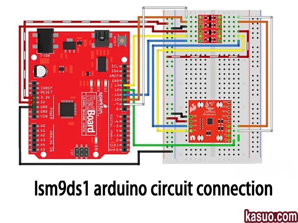
In this circuit, the LSM9DS1 sensor is connected to the Arduino RedBoard via I2C communication. Here’s a simple breakdown:
The VCC pin (red wire) connects to the RedBoard’s 3.3V output since the LSM9DS1 operates at 3.3V. The GND pin (black wire) goes to the RedBoard’s GND to complete the circuit. The SCL (yellow wire) connects to the A5 pin (I2C clock), and SDA (blue wire) connects to A4 (I2C data line).
The CS pin (orange wire) isn’t connected here since it’s not needed when using I2C. The SDO pin (green wire) is grounded, setting the device address to 0x6A.
The INT1 and INT2 pins (white and brown wires) can be connected to Arduino’s digital pins if you’re using interrupts, but they’re optional for basic use.
Remember, always use the correct I2C address in your code, and avoid using the RedBoard’s 5V pin to power the LSM9DS1 to prevent damage. If using interrupts, connect the appropriate pins for event-driven programming.
lsm9ds1 orientation detection、
The LSM9DS1 sensor is a 9-axis sensor that combines an accelerometer, gyroscope, and magnetometer, making it perfect for applications like motion tracking, posture detection, and navigation. The accelerometer measures acceleration and tilt angles, letting you track the device’s pitch and roll. You can calculate the acceleration in the X, Y, and Z axes and figure out the tilt angle from these readings.
The gyroscope tracks rotational speed, helping you monitor how the device is rotating along each axis. The magnetometer, on the other hand, detects the Earth’s magnetic field, helping determine the device’s orientation or heading.
To improve posture detection accuracy, many use data fusion algorithms like complementary or Kalman filtering to combine these readings, reducing noise and drift for stable and accurate results. The LSM9DS1 communicates with microcontrollers via I2C or SPI, offering low power consumption and high precision, making it great for wearables, drones, and robotics.
lsm9ds1 i2c address conflict
If you’re using the LSM9DS1 sensor and facing an I2C address conflict, it’s likely because two devices on your I2C bus have the same address. Each I2C device has a unique address to distinguish it from others, and when two devices share the same address, the communication won’t work properly.
For the LSM9DS1, there are two possible I2C addresses depending on how you connect the SDO_AG and SDO_M pins. By default, the accelerometer and gyroscope address is 0x6B, and the magnetometer is 0x1C. If you ground the SDO_AG pin, the accelerometer and gyroscope address changes to 0x6A, while the magnetometer becomes 0x1E.
To fix any address conflicts, check the addresses of all connected devices. If needed, change the LSM9DS1 address by adjusting the SDO_AG and SDO_M pins. If you can’t change the address, use an I2C multiplexer like the TCA9548A to assign unique addresses to each device. Also, double-check your connections to avoid any short circuits that might mess up communication.
lsm9ds1 kalman filter usage
When you’re working with the LSM9DS1 sensor for attitude estimation, the Kalman filter is a powerful tool to fuse data from the accelerometer, gyroscope, and magnetometer. This filter helps to improve accuracy by minimizing noise in the sensor data, especially when you’re dealing with systems that have significant noise.
Here’s how it works: the Kalman filter uses a two-step process—prediction and update. First, it predicts the current state based on the system’s model. Then, it compares the predicted state with actual sensor measurements and updates the estimate to correct any errors. This process helps stabilize the attitude estimation, especially when you’re dealing with drift from the gyroscope or noise from the accelerometer and magnetometer.
By combining the strengths of each sensor, the Kalman filter gives you accurate pitch, roll, and yaw angles, ensuring your system’s stability in dynamic environments. Just remember, for optimal performance, you should fine-tune the filter’s noise matrix and calibrate the sensors properly.
lsm9ds1 sensor fusion library
When you’re using the LSM9DS1 sensor for sensor fusion, having the right library can make the process a lot smoother. There are several libraries that can help you combine the accelerometer, gyroscope, and magnetometer data for accurate attitude estimation.
The Adafruit LSM9DS1 library is great for basic sensor data reading. It gives you access to the sensor’s data but doesn’t handle the fusion itself, so you’ll need to write your own algorithm for that.
If you’re looking for a complete solution, RTIMULib offers an advanced sensor fusion library. It handles all the heavy lifting of data fusion and provides reliable attitude estimation for more complex applications.
For a more efficient fusion algorithm, the Madgwick Filter library is an excellent choice. It’s designed specifically for combining accelerometer, gyroscope, and magnetometer data, giving you stable results for attitude estimation.
By choosing the right library, you’ll be able to integrate LSM9DS1 with Arduino easily and get precise results for your projects.
lsm9ds1 wiring with esp32

When connecting the LSM9DS1 sensor to your ESP32, here’s a simple guide to get you started. First, connect the power (VCC) and ground (GND) pins of the LSM9DS1 to the 3.3V and GND rails on your breadboard. For I2C communication, wire the SCL (clock) and SDA (data) pins from the sensor to GPIO 22 and GPIO 21 on the ESP32—these are the default I2C pins. The SDO_AG and SDO_M pins should be connected to GND to set the default I2C address.
Make sure the ESP32 gets power via the USB cable, and check that all the connections are secure. If you need to change the I2C address, simply adjust the SDO_AG and SDO_M pins to VCC or GND. Lastly, in your Arduino IDE, make sure you’ve selected the correct ESP32 board and installed the necessary drivers.
Double-check that SDA and SCL are properly connected, and you should be all set!
More Like This

SF4-AH64-H
Panasonic Industrial Automation Sales
SF4-AH64
Panasonic Industrial Automation Sales
SF4-AH56-N
Panasonic Industrial Automation Sales
SF4-AH56-H
Panasonic Industrial Automation Sales
SF4-AH56
Panasonic Industrial Automation Sales
SF4-AH48-N
Panasonic Industrial Automation Sales
SF4-AH48-H
Panasonic Industrial Automation Sales
SF4-AH48
Panasonic Industrial Automation Sales
SF4-AH40-N
Panasonic Industrial Automation Sales
SF4-AH40-H
Panasonic Industrial Automation Sales
SF4-AH40
Panasonic Industrial Automation Sales
SF4-AH36-N
Panasonic Industrial Automation Sales
Also Add to Cart

114990093
Seeed Technology Co., Ltd
DP11SVN20B30F
TE Connectivity ALCOSWITCH Switches

CS-0302-13
Alliance

WBP-SC-0015-01
Digital Six Labs
3455R02570016
Honeywell Sensing and Productivity Solutions

HO 25-NP-0000
LEM USA Inc.
62S11-H9-040C
Grayhill Inc.

TSOP59356TR
Vishay Semiconductor Opto Division
NJL7302L-F3
Nisshinbo Micro Devices Inc.

AD7817BRUZ-REEL
Analog Devices Inc.
62A11-01-060S
Grayhill Inc.
IDG-2021S
TDK InvenSense
Related Products
SF4-AH64-H
Panasonic Industrial Automation Sales
SF4-AH64
Panasonic Industrial Automation Sales
SF4-AH56-N
Panasonic Industrial Automation Sales
SF4-AH56-H
Panasonic Industrial Automation Sales
SF4-AH56
Panasonic Industrial Automation Sales
SF4-AH48-N
Panasonic Industrial Automation Sales
SF4-AH48-H
Panasonic Industrial Automation Sales
SF4-AH48
Panasonic Industrial Automation Sales
SF4-AH40-N
Panasonic Industrial Automation Sales
SF4-AH40-H
Panasonic Industrial Automation Sales
SF4-AH40
Panasonic Industrial Automation Sales
SF4-AH36-N
Panasonic Industrial Automation Sales
SF4-AH36-H
Panasonic Industrial Automation Sales
SF4-AH36
Panasonic Industrial Automation Sales
SF4-AH32-N
Panasonic Industrial Automation Sales
SF4-AH32-H
Panasonic Industrial Automation Sales
SF4-AH32
Panasonic Industrial Automation Sales
SF4-AH28-N
Panasonic Industrial Automation Sales
SF4-AH28-H
Panasonic Industrial Automation Sales
SF4-AH28
Panasonic Industrial Automation Sales
SF4-AH24-N
Panasonic Industrial Automation Sales
SF4-AH24-H
Panasonic Industrial Automation Sales
SF4-AH24
Panasonic Industrial Automation Sales
SF4-AH20-N
Panasonic Industrial Automation Sales
SF4-AH20-H
Panasonic Industrial Automation Sales
SF4-AH20
Panasonic Industrial Automation Sales
SF4-AH16-N
Panasonic Industrial Automation Sales
SF4-AH16-H
Panasonic Industrial Automation Sales
SF4-AH16
Panasonic Industrial Automation Sales
SF4-AH12-N
Panasonic Industrial Automation Sales
Please send RFQ , we will respond immediately.
