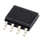
INA128 Amplificador y hoja de datos | Distribución de pines
- Marcas: Texas Instruments
- Descargar: -
- Precio: consulta
- En stock: 8865
- Contacto Género: -
- Material: -
- Diámetro máximo del paquete: -
- Paquete: -

Envío GRATUITO para pedidos superiores a HK$250.00

Respuesta rápida, cotización rápida.

Envío rápido, sin preocupaciones posventa.

Canal original, garantía de los productos auténticos.
Key Features of the INA128 Precision Instrumentation Amplifier
El INA128 is a low-power, precision instrumentation amplifier designed for accurate, low-noise measurements. It offers a high common-mode rejection ratio (CMRR) and excellent accuracy, making it ideal for amplifying differential signals in noisy environments. With a wide input voltage range and low offset voltage, the INA128 is perfect for applications like sensor signal conditioning, medical devices, and data acquisition systems. Its adjustable gain allows flexibility in different use cases, and its low power consumption ensures efficiency in battery-powered systems. Whether you’re designing for industrial automation or biomedical applications, the INA128 provides reliable and precise signal amplification.
INA128 Pinout
| Alfiler | Label | Descripción |
|---|---|---|
| 1 | V+ | Positive power supply pin, typically connected to +5V or +15V. |
| 2 | -IN | Negative input pin for differential signals. |
| 3 | +IN | Positive input pin for differential signals. |
| 4 | RG | External resistor for setting the gain of the amplifier. |
| 5 | V- | Negative power supply pin, typically connected to -5V or ground. |
| 6 | Producción | Output pin for the amplified differential signal. |
| 7 | Ref | Reference input pin, typically connected to ground or a reference voltage. |
| 8 | CAROLINA DEL NORTE | No connection (unused pin). |
Using the INA128 Pinout
El INA128 is a precision instrumentation amplifier used to amplify differential signals. The V+ (Pin 1) and V- (Pin 5) are the power supply pins, providing the necessary voltage for operation. The differential inputs are applied to +IN (Pin 3) and -IN (Pin 2), with the signal being amplified based on the voltage difference. RG (Pin 4) is used to set the gain by connecting an external resistor, and Ref (Pin 7) sets the reference voltage for the output. The Producción (Pin 6) provides the amplified signal. Make sure the power supply voltage is stable and within the recommended range to ensure proper functioning of the INA128. Always use proper grounding and signal conditioning for optimal performance.
INA128 Equivalent Models
Here’s a comparison of equivalent precision instrumentation amplifiers with similar packaging and features:
| Modelo | Rango de voltaje de entrada | Gain Range | CMRR | Voltaje de compensación | Voltaje de suministro | Tipo de paquete | Características principales |
|---|---|---|---|---|---|---|---|
| INA128 | ±10V to ±18V | 1 to 1000 | 120dB | 50µV | ±2.25V to ±18V | SOIC-8 | High precision, low power consumption |
| INA333 | ±10V to ±18V | 1 to 1000 | 100dB | 25µV | ±2.3V to ±18V | SOIC-8 | Low offset, high accuracy, low power |
| INA826 | ±0.6V to ±40V | 1 to 1000 | 120dB | 25µV | ±2.25V to ±40V | SOIC-8 | Low power, wide supply range, low offset |
| 620 d. C. | ±2V to ±18V | 1 to 1000 | 100dB | 50µV | ±2.3V to ±18V | SOIC-8 | High accuracy, flexible input range |
Substitution Tips
When replacing the INA128, make sure to match key parameters like the input voltage range, gain range, y CMRR (common-mode rejection ratio). For example, the INA333 is a great alternative, offering lower offset voltage and similar performance in terms of gain and CMRR. The INA826 also provides excellent precision with a wider supply voltage range, making it suitable for applications that need a bit more flexibility. If you need a cost-effective option with similar performance, the 620 d. C. is a good choice but with a slightly lower CMRR. Always verify that the tensión de alimentación y tipo de paquete align with your design to ensure compatibility.
INA128 on Amazon
El INA128 is available on platforms like Amazon, making it easy for engineers and hobbyists to source this precision instrumentation amplifier. It’s often used in power supply systems, sensor signal conditioning, and other applications requiring high accuracy and low noise. Purchasing from Amazon can be convenient, with options for fast shipping and reliable customer service. Be sure to check the seller’s ratings and reviews to ensure you’re getting genuine components.
INA128 Application
El INA128 is widely used in a variety of applications where precise signal amplification is necessary. It’s perfect for sensor signal conditioning, including temperature, pressure, and light sensors. Its high common-mode rejection ratio (CMRR) makes it ideal for use in noisy environments, like industrial control systems. The adjustable gain feature allows it to be customized for different systems, and it’s commonly used in medical devices, audio processing, and data acquisition systems, providing accurate readings and stable performance.
INA128 Circuit Diagram and Analysis
El INA128 is a precision instrumentation amplifier widely used in sensor signal conditioning, medical instrumentation, and data acquisition systems. Below is a simplified circuit diagram illustrating its basic connections:
Circuit Components and Functionality
-
RG (Pin 1): This external resistor sets the gain of the amplifier. The gain is determined by the formula:
Gain (G) = 1 + (50 kΩ / RG)
For example, a 50 kΩ resistor will set the gain to 2.
-
V+ (Pin 2) and V− (Pin 3): These are the power supply pins, typically connected to positive and negative voltages, respectively, such as ±5V or ±15V.
-
Vout (Pin 5): This is the output pin where the amplified differential signal is available.
-
Ref (Pin 8): The reference pin sets the output voltage reference. It is often connected to ground or a mid-supply voltage, depending on the application.
-
Vin+ (Pin 4) and Vin− (Pin 6): These are the positive and negative input pins, respectively, where the differential signal is applied.
Application Example: Electrocardiogram (ECG) Front-End
In an ECG application, the INA128 can be used to amplify the small voltage signals from the heart. The inputs (Vin+ and Vin−) would be connected to electrodes placed on the body, and the output (Vout) would be fed into an analog-to-digital converter (ADC) for further processing. The gain is set appropriately to amplify the heart’s electrical signals to a level suitable for digital processing.
Key Considerations
-
Fuente de alimentación: Ensure that the power supply voltages are within the specified range for the INA128 to operate correctly.
-
Rango de voltaje de entrada: The input voltages should be within the common-mode range of the amplifier to avoid distortion or saturation.
-
Gain Setting: Choose the appropriate value for RG to set the desired gain, keeping in mind the input signal levels and the required output range.
-
Reference Pin: Properly bias the reference pin to set the output voltage reference, ensuring accurate signal representation.
For more detailed information, refer to the INA128 datasheet:


