
IRFP250N Datasheet, Amplifier Circuit, Price
- Tipo de transistor: 1 canal N
- Tiempo típico de retardo de apagado: 41 ns
- Tiempo de retardo de encendido típico: 14 ns
- Paquete: -


Envío GRATUITO para pedidos superiores a HK$250.00

Respuesta rápida, cotización rápida.

Envío rápido, sin preocupaciones posventa.

Canal original, garantía de los productos auténticos.
Транзистор полевой IRFP250N
Irfp250n
If you’re considering the IRFP250N MOSFET for your project, here’s what you need to know. This N-channel MOSFET can handle up to 250V for drain-to-source voltage and 51A of current, making it ideal for medium to high-power applications like motor drivers, power supplies, and switching converters.
One of its standout features is its low on-resistance (Rds(on) = 0.08Ω), which helps reduce power loss and improve efficiency, especially in high-current applications. It also has good switching characteristics, making it suitable for high-frequency applications like PWM control or motor control.
The IRFP250N also performs well in high-temperature environments, with a working temperature range of -55°C to +150°C, so it’s great for harsh conditions. You’ll find this MOSFET in power converters, motor drives, audio amplifiers, and UPS systems, where high voltage and current handling are essential.
Irfp250n Pinout
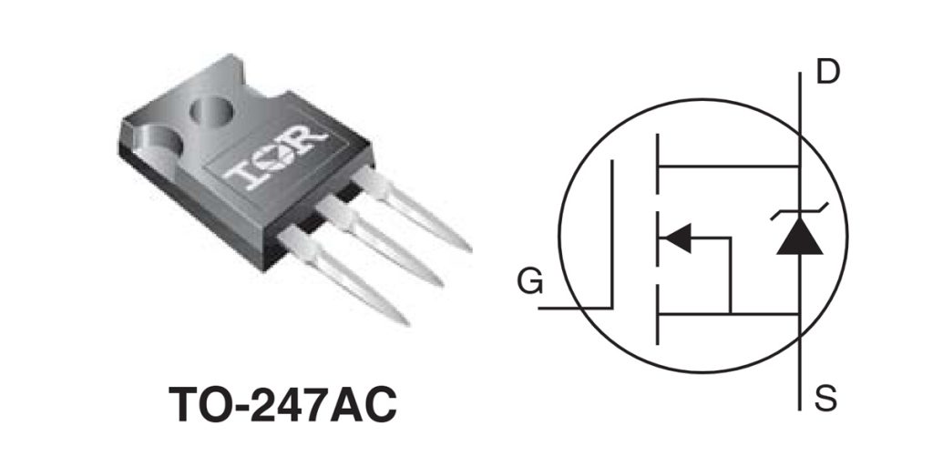
| Número PIN | Nombre del pin | Descripción |
|---|---|---|
| 1 | Puerta (G) | Gate pin, controls the ON/OFF state of the MOSFET. It controls the MOSFET’s switching through the gate-source voltage (Vgs). |
| 2 | Drenaje (D) | Drain pin, the current flows out of the MOSFET. It connects to the load or the high-voltage side of the circuit. |
| 3 | Fuente (S) | Source pin, the current flows into the MOSFET. It connects to the low-voltage side or ground of the circuit. |
When working with the IRFP250N MOSFET, here’s what you should keep in mind:
-
Puerta (G): The gate controls the MOSFET’s on/off state. To fully turn it on, you need a gate voltage of about 10V. If it’s lower than that (like 5V or less), the MOSFET won’t fully turn on, leading to higher resistance and lower efficiency. Using a PWM signal to control the gate voltage will help achieve efficient switching.
-
Drenaje (D): The drain is where the current exits the MOSFET and flows to the load. Make sure the voltage across the drain and source doesn’t exceed 250V, or you risk damaging the MOSFET.
-
Fuente (S): The source is where current enters the MOSFET. Ensure it’s securely connected to ground or the negative side of the power supply.
Consejos:
-
Make sure the gate voltage is high enough (around 10V) to avoid inefficiency and heat.
-
Proper cooling, like heat sinks, is essential when using this MOSFET in high-current applications.
-
Consider adding a protection diode to prevent damage from reverse current.
Irfp250n Equivalent

| Parámetro | IRFP250N | IRFP260N | STP55NF06L | FQP30N06L | IRLZ44N |
|---|---|---|---|---|---|
| Maximum Drain-Source Voltage (Vds) | 250 V | 200 V | 60 V | 60 V | 55 V |
| Maximum Drain Current (Id) | 51A | 50A | 55A | 30A | 47A |
| On-Resistance (Rds(on)) | 0.08Ω | 0.04Ω | 0.022Ω | 0.030Ω | 0.022Ω |
| Gate Threshold Voltage (Vgs(th)) | 2-4V | 2-4V | 1-3V | 1-3V | 1-2V |
| Maximum Power Dissipation (Pd) | 150 W | 200 W | 150 W | 75W | 55W |
| Tipo de paquete | TO-220 | TO-247 | TO-220 | TO-220 | TO-220 |
| Switching Speed | Fast | Fast | Fast | Fast | Fast |
| Operating Temperature Range | -55°C a +150°C | -55°C to +125°C | -55°C a +150°C | -55°C a +150°C | -55°C a +150°C |
When choosing a replacement for the IRFP250N, here’s what you need to consider:
-
Maximum Drain-to-Source Voltage: The IRFP250N can handle up to 250V, making it a solid choice for high-voltage applications. If your voltage requirements are lower, you might want to consider the IRFP260N (200V) or other lower-voltage MOSFETs like the STP55NF06L or FQP30N06L.
-
On-Resistance (Rds(on)): A lower Rds(on) means better efficiency, with less power loss. If you need high efficiency, the IRFP260N and IRLZ44N offer lower Rds(on) compared to the IRFP250N.
-
Corriente máxima: Most replacements offer similar current ratings, around 51A, but models like the IRFP260N and STP55NF06L can handle even higher currents, making them suitable for more demanding applications.
-
Disipación de potencia: If your application requires handling more power, consider the IRFP260N, which has higher power handling capacity.
-
Package and Temperature Range: If you need a different package, many alternatives like IRLZ44N also come in the TO-220 package. Ensure the operating temperature range (-55°C to +150°C) is suitable for your environment.
Choosing the right replacement depends on your voltage, current, and power needs, so make sure to match these carefully.
Irfp250n High Voltage Switching Circuit

In this circuit, the IRFP250N MOSFET is the key switching component, working alongside a transformer, diodes, inductors, capacitors, and resistors to handle high-voltage switching operations. The goal is to control the current output by adjusting the MOSFET’s switching state, which is commonly used in high-current, high-voltage applications like inverters or power converters.
Here’s how it works: The transformer converts 200V AC input to a voltage suitable for the circuit. The diode (D1) then rectifies the AC into DC, and the capacitor (C1) smooths out the current, reducing noise and voltage spikes that could affect the MOSFET.
The MOSFET’s gate voltage (controlled by resistors R1 and R2) turns the IRFP250N on and off, allowing current to pass through the inductor (L1), which limits current rise and smooths out current spikes.
This circuit is ideal for high-power applications such as motor drives, power supplies, and UPS systems, where efficient high-voltage and high-current switching is necessary.
Irfp250n For H-bridge Inverter
In an H-Bridge inverter circuit, the IRFP250N MOSFET plays a key role as the switching element, enabling high-voltage and high-current operations. It helps convert DC into AC by controlling the current direction through alternating switching of the four MOSFETs in the H-Bridge configuration.
Here’s how it works: The four MOSFETs—Q1, Q2, Q3, and Q4—are controlled by PWM signals, which dictate the opening and closing of each MOSFET. This switching creates alternating current (AC) at the load. In the circuit, Q1 and Q2 are the upper switches, while Q3 and Q4 are the lower ones. By switching them alternately, you can generate AC.
The IRFP250N is perfect for this application because it handles up to 250V and 51A, with a low on-resistance (0.08Ω), ensuring efficient power transfer. When designing, make sure to use a gate driver circuit to provide the necessary gate voltage (above 10V) for full MOSFET conduction. Also, don’t forget about dead-time management to avoid short circuits during switching.
Irfp250n vs Irfp460n
| Parámetro | IRFP250N | IRFP460N |
|---|---|---|
| Maximum Drain-Source Voltage (Vds) | 250 V | 500 V |
| Maximum Drain Current (Id) | 51A | 20A |
| On-Resistance (Rds(on)) | 0.08Ω | 0.27Ω |
| Gate Threshold Voltage (Vgs(th)) | 2-4V | 2-4V |
| Maximum Power Dissipation (Pd) | 150 W | 150 W |
| Tipo de paquete | TO-220 | TO-220 |
| Switching Speed | Fast | Medium |
| Operating Temperature Range | -55°C a +150°C | -55°C a +150°C |
When choosing between the IRFP250N and IRFP460N, here’s what you need to consider:
-
Clasificación de voltaje: The IRFP460N handles a higher voltage (500V), making it ideal for high-voltage applications like power supplies and inverters. If your application requires over 250V, the IRFP460N is the better choice. On the other hand, the IRFP250N supports up to 250V, suitable for lower voltage setups.
-
Calificación actual: The IRFP250N can handle up to 51A, perfect for high-current applications, whereas the IRFP460N supports 20A, which is better suited for medium current loads.
-
On-Resistance (Rds(on)): The IRFP250N has a lower Rds(on) of 0.08Ω, meaning it’s more efficient and generates less heat, especially in high-current applications. The IRFP460N’s Rds(on) is higher at 0.27Ω, making it less efficient in comparison.
-
Switching Speed: The IRFP250N has faster switching speeds, making it great for high-frequency applications, while the IRFP460N is slower and better for low-frequency use.
In short, choose the IRFP250N for efficiency and high-current, low-voltage needs, and the IRFP460N for high-voltage, medium-current applications.
Irfp250n Gate Resistor Selection
When using the IRFP250N MOSFET, choosing the right gate resistor is key to controlling switching speed, reducing power loss, and ensuring circuit stability. The gate resistor helps manage the rise and fall times of the gate voltage, preventing excessive current spikes, reducing noise, and minimizing electromagnetic interference (EMI).
The gate charge (Qg) of the IRFP250N is around 130nC, so the resistor you select should balance switching speed and efficiency. For high-frequency applications, a lower gate resistor (like 10Ω) speeds up switching but may cause more EMI. A higher value (like 100Ω) slows down the switching, reducing EMI but potentially affecting speed.
For low-frequency applications, like a few kHz, you might go with 47Ω or 100Ω to cut down on noise. For high-frequency switching, 10Ω or 22Ω is better, but make sure your gate driver can handle the current. For most applications, 22Ω to 47Ω gives a good balance between speed and noise control.
Más como esto

RBQ20NS65AFHTL
Semiconductor Rohm

V20D100C-M3/I
Vishay General Semiconductor - División de Diodos
V20D60C-M3/I
Vishay General Semiconductor - División de Diodos

BYV32E-200PQ
Semiconductores WeEn
VT2060C-E3/4W
Vishay General Semiconductor - División de Diodos

30CTQ050-1
Soluciones de diodos SMC

30CTQ045-1
Soluciones de diodos SMC

30CTQ040-1
Soluciones de diodos SMC

SR2060
Corporación de Semiconductores de Taiwán
SR2040
Corporación de Semiconductores de Taiwán
MBR2060CT
Corporación de Semiconductores de Taiwán
GP1606
Corporación de Semiconductores de Taiwán
Añadir también al carrito

CQDD-16M BK
Corporación Central de Semiconductores

Q4004F42
Littelfuse Inc.

DTA115TUAT106
Semiconductor Rohm

L4008D6RP
Littelfuse Inc.

UP0421000L
Componentes electrónicos de Panasonic
IXA27IF1200HJ
IXYS
T7SH084044DN
Powerex Inc.

NXV65HR82DS1
onsemi
VHFD29-14IO1
IXYS

K2000GHU
Littelfuse Inc.

VS-25RIA20
Vishay General Semiconductor - División de Diodos
SVC388S-AL
onsemi
Productos relacionados
RBQ20NS65AFHTL
Semiconductor Rohm
V20D100C-M3/I
Vishay General Semiconductor - División de Diodos
V20D60C-M3/I
Vishay General Semiconductor - División de Diodos
BYV32E-200PQ
Semiconductores WeEn
VT2060C-E3/4W
Vishay General Semiconductor - División de Diodos
30CTQ050-1
Soluciones de diodos SMC
30CTQ045-1
Soluciones de diodos SMC
30CTQ040-1
Soluciones de diodos SMC
SR2060
Corporación de Semiconductores de Taiwán
SR2040
Corporación de Semiconductores de Taiwán
MBR2060CT
Corporación de Semiconductores de Taiwán
GP1606
Corporación de Semiconductores de Taiwán

MBRS1045CTH
Corporación de Semiconductores de Taiwán
16CTQ150
Soluciones de diodos SMC

V10D45CHM3_A/I
Vishay General Semiconductor - División de Diodos
NRVHP8H200MFDWFT3G
onsemi

VBT1545CBP-E3/4W
Vishay General Semiconductor - División de Diodos
VBT1545CBP-E3/8W
Vishay General Semiconductor - División de Diodos
MBR2080CT-G
Tecnología Comchip
MBR2060CT-G
Tecnología Comchip
MBR2050CT-G
Tecnología Comchip
MBR2040CT-G
Tecnología Comchip
MBR2030CT-G
Tecnología Comchip
UGB10DCT-E3/45
Vishay General Semiconductor - División de Diodos
UGB10CCT-E3/45
Vishay General Semiconductor - División de Diodos
UGB10BCT-E3/45
Vishay General Semiconductor - División de Diodos

SDUR3020CT
Soluciones de diodos SMC

RBQ15BM45AFHTL
Semiconductor Rohm

SDUR3040CT
Soluciones de diodos SMC

V10K170C-M3/H
Vishay General Semiconductor - División de Diodos
Envíe RFQ, le responderemos de inmediato.
