
LSM6DSOX marking, datasheet & adafruit | arduino
- Resolución: -
- Tipo de sensor: -
- Tipo de salida: -
- Paquete: -


Envío GRATUITO para pedidos superiores a HK$250.00

Respuesta rápida, cotización rápida.

Envío rápido, sin preocupaciones posventa.

Canal original, garantía de los productos auténticos.
Getting Started with LSM6DSOX
Lsm6dsox
The LSM6DSOX is a versatile six-axis inertial sensor by STMicroelectronics, combining a three-axis accelerometer and a three-axis gyroscope to measure linear acceleration and angular velocity. It’s perfect for applications like motion tracking, posture monitoring, and navigation. The accelerometer can be set to measure different ranges like ±2g, ±4g, ±8g, and ±16g, while the gyroscope has ranges from ±125°/s to ±2000°/s. It features digital output via I²C or SPI, with a high data output rate of up to 6KHz, making it great for real-time applications. Plus, it’s energy-efficient, offering low-power modes for portable devices and wearables. The sensor also supports motion detection functions like step counting and free fall detection, making it ideal for smart gadgets. With a compact design and high electromagnetic interference resistance, it’s perfect for use in both consumer and industrial environments.
Lsm6dsox Pinout
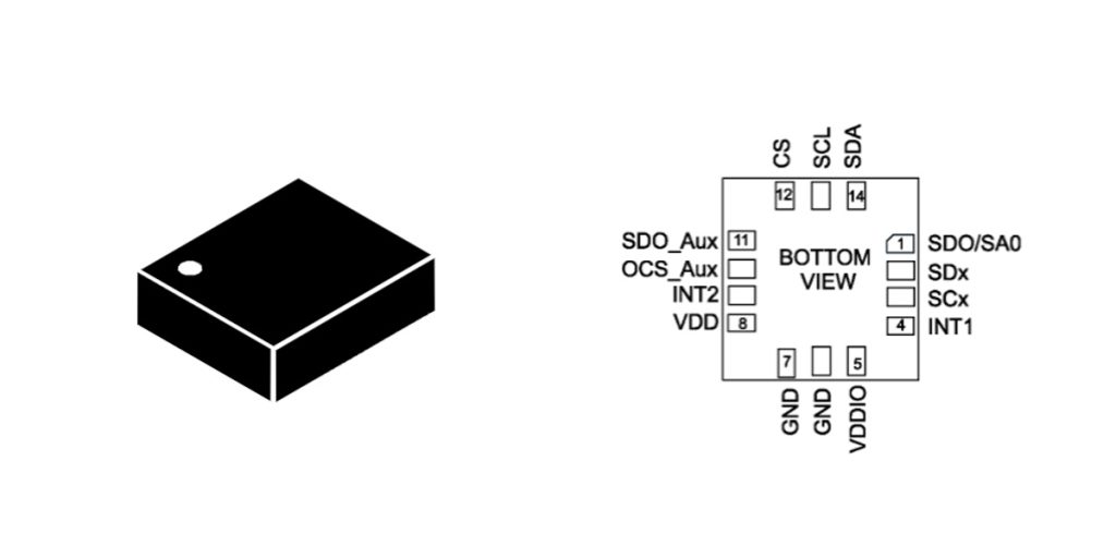
| Número PIN | Nombre del pin | Descripción de la función |
|---|---|---|
| 1 | VDD | Power input (3.3V) |
| 2 | Tierra | Suelo |
| 3 | SCL | I2C clock line, or SPI clock line |
| 4 | Adventista del Séptimo Día | I2C data line, or SPI data input (MISO) |
| 5 | CS | SPI chip select, used to activate the device |
| 6 | INT1 | External interrupt 1 output |
| 7 | INT2 | External interrupt 2 output |
| 8 | SD0 | I2C data line, or SPI data output (MOSI) |
| 9 | VCAP | Internal voltage regulator capacitor pin |
| 10 | Organización de Desarrollo de los Recursos Naturales (SDO) | SPI data output |
| 11 | SCK | SPI clock line |
| 12 | VDDIO | Power input (supports 1.8V or 3.3V) |
| 13 | CAROLINA DEL NORTE | No connection, can be ignored |
| 14 | RES / NC | Reserved or No Connection (should be left floating if NC) |
When working with the LSM6DSOX, make sure to connect the power pins properly. The VDD pin should go to a stable 3.3V supply, while the GND pin connects to ground. VDDIO is for powering the I²C or SPI interface, typically set to 3.3V or 1.8V, depending on your controller.
For communication, you have two options: I²C or SPI. For I²C, connect the SCL and SDA pins for clock and data. In SPI mode, you’ll use SCK, MISO, MOSI, and CS pins for communication.
The INT1 and INT2 pins are for interrupt functions, like detecting steps or free fall. You may need external pull-up or pull-down resistors for these.
Lastly, don’t forget the VCAP pin, which connects a capacitor to ensure stable internal voltage regulation. The NC (not connected) pin doesn’t require any wiring.
Make sure the voltage settings match your MCU’s requirements, and carefully choose the right communication interface for your project.
Lsm6dsox Equivalent Motion Sensor


| Parámetros | LSM6DSOX | LSM6DSL | MPU6050 | ICM-20608 |
|---|---|---|---|---|
| Rango de aceleración | ±2g, ±4g, ±8g, ±16g | ±2g, ±4g, ±8g, ±16g | ±2g, ±4g, ±8g, ±16g | ±2g, ±4g, ±8g, ±16g |
| Alcance del giroscopio | ±125°/s, ±250°/s, ±500°/s, ±1000°/s, ±2000°/s | ±125°/s, ±250°/s, ±500°/s, ±1000°/s, ±2000°/s | ±250°/s, ±500°/s, ±1000°/s, ±2000°/s | ±1000°/s, ±2000°/s |
| Interface Type | I2C, SPI | I2C, SPI | I2C, SPI | I2C, SPI |
| Resolución | 16 bits | 16 bits | 16 bits | 16 bits |
| Voltaje de operación | 1.71V – 3.6V | 1.8V – 3.6V | 2.375V – 3.46V | 2.4V – 3.6V |
| Current Consumption | 1.2mA (Accelerometer and gyroscope enabled) | 0.7mA (Accelerometer and gyroscope enabled) | 3.9mA (Accelerometer and gyroscope enabled) | 3.9mA (Accelerometer and gyroscope enabled) |
| Internal Functions | Step counter, free-fall detection, activity detection | Step counter, free-fall detection, activity detection | Step counter, free-fall detection, activity detection | Step counter, free-fall detection, activity detection |
| Tipo de paquete | LGA-16 | LGA-16 | QFN-24 | LGA-24 |
| Operating Temperature Range | -40°C a +85°C | -40°C a +85°C | -40°C a +85°C | -40°C a +85°C |
When choosing an alternative to the LSM6DSOX, there are a few things you need to consider. First, check the range and accuracy of the sensor—make sure it matches the needs of your application. The LSM6DSOX, LSM6DSL, MPU6050, and ICM-20608 all offer similar acceleration and gyroscope ranges, but you’ll want to ensure they fit your specific requirements.
If low power is essential, the LSM6DSOX and LSM6DSL are great choices, as they consume less power (1.2mA and 0.7mA, respectively) compared to the MPU6050 and ICM-20608 (3.9mA).
These sensors also support I²C and SPI, so make sure the communication protocol is compatible with your system. The LSM6DSOX and LSM6DSL have built-in features like step counting and free fall detection, which are great for applications that need more functionality.
Finally, pay attention to the packaging. The LSM6DSOX and LSM6DSL use LGA-16, while the MPU6050 and ICM-20608 use QFN-24 and LGA-24, which may be a consideration if space is tight.
Lsm6dsox Motion Tracking Circuit
![]()
The LSM6DSOX sensor combines both an accelerometer and a gyroscope, offering 3-axis acceleration and 3-axis angular velocity measurements. It’s perfect for motion tracking applications. By connecting via I²C or SPI to a microcontroller like ESP32, STM32, or Arduino, you can use the sensor’s data to track movement.
The INT1 and INT2 interrupt pins play a key role here, providing real-time responses to motion events like step counting, activity mode switching, and fall detection. These interrupts are critical for efficient motion tracking.
By configuring the LSM6DSOX’s features like gait detection and activity monitoring, you can easily create applications for wearables, smartwatches, or even virtual reality systems.
In short, the LSM6DSOX sensor, connected via I²C or SPI, enables effective motion tracking. With interrupt pins for motion event responses, it’s ideal for tracking applications, giving you precise data for accurate movement detection in your projects.
Lsm6dsox Sensor Hub Example
With the LSM6DSOX sensor, you can easily combine multiple sensors like an accelerometer, gyroscope, and even external ones such as a magnetometer, all within a single device. This allows you to process raw data and perform simple sensor fusion, such as step counting, motion recognition, and position estimation.
The sensor communicates with your main controller (like an MCU or embedded system) via I²C or SPI. Your controller processes the data using algorithms to enable more advanced functions, making it ideal for applications like wearable devices.
For instance, you can use LSM6DSOX for step counting, detecting free falls, and posture changes. By combining data from the accelerometer, gyroscope, and magnetometer, you can create a comprehensive motion tracking system. This can be used in various devices such as smart bands, glasses, and other wearables, providing real-time tracking and movement recognition.
Lsm6dsox I2c Configuration
I²C Pin Connection
| Nombre del pin | Descripción de la función |
|---|---|
| Adventista del Séptimo Día | Data line (I2C data transfer) |
| SCL | Clock line (I2C clock) |
| VDD | Power input (typically 3.3V) |
| Tierra | Ground (connected to ground) |
| CS | Chip select pin, I2C mode (connected to VDD or 3.3V) |
| SDO/SA0 | I2C address selection pin, used to select the I2C address 0x6A or 0x6B when connected to VDD or GND |
When setting up the LSM6DSOX sensor for I²C communication, there are a few key things to remember. First, you’ll connect the SDA and SCL pins for data and clock, respectively. For power, connect VDD to a stable 3.3V source, and ground (GND) to the system ground. You’ll also use the CS pin, which should be set to a high level (VDD) in I²C mode. The SDO/SA0 pin helps you choose between two I²C addresses: 0x6A when connected to ground or 0x6B when connected to VDD.
Once everything is connected, you’ll initialize the communication with your microcontroller using a library like Wire for Arduino. From there, you can configure various registers, like setting the accelerometer’s range or reading raw data. You can also set up interrupts like step detection or free-fall by configuring INT1 and INT2 pins. Always make sure the voltage is stable and the I²C rate is properly set for reliable data transfer.
Lsm6dsox Arduino Sample Vode、
Arduino Example Code:
#include <Wire.h> // Include Wire library to support I²C communication
#define LSM6DSOX_ADDRESS 0x6A // Default I²C address of LSM6DSOX
void setup() {
Serial.begin(115200); // Initialize serial communication with 115200 baud rate
Wire.begin(); // Initialize I²C communication
// Initialize LSM6DSOX sensor
initializeLSM6DSOX();
Serial.println(“LSM6DSOX I2C Example”);
}
void loop() {
// Read accelerometer and gyroscope data
readAccelerometer();
readGyroscope();
delay(500); // Delay for 500 milliseconds
}
// Initialize LSM6DSOX sensor
void initializeLSM6DSOX() {
Wire.beginTransmission(LSM6DSOX_ADDRESS);
Wire.write(0x10); // Address of accelerometer range control register
Wire.write(0x00); // Set range to ±2g
Wire.endTransmission();
Wire.beginTransmission(LSM6DSOX_ADDRESS);
Wire.write(0x11); // Address of gyroscope range control register
Wire.write(0x00); // Set range to ±250°/s
Wire.endTransmission();
}
// Read accelerometer data
void readAccelerometer() {
Wire.beginTransmission(LSM6DSOX_ADDRESS);
Wire.write(0x28); // Accelerometer data register address
Wire.endTransmission();
Wire.requestFrom(LSM6DSOX_ADDRESS, 6); // Request 6 bytes of data (2 bytes for each axis)
int ax = (Wire.read() | (Wire.read() << 8)); // X-axis data
int ay = (Wire.read() | (Wire.read() << 8)); // Y-axis data
int az = (Wire.read() | (Wire.read() << 8)); // Z-axis data
Serial.print(“Accel X: “);
Serial.print(ax);
Serial.print(” Y: “);
Serial.print(ay);
Serial.print(” Z: “);
Serial.println(az);
}
// Read gyroscope data
void readGyroscope() {
Wire.beginTransmission(LSM6DSOX_ADDRESS);
Wire.write(0x22); // Gyroscope data register address
Wire.endTransmission();
Wire.requestFrom(LSM6DSOX_ADDRESS, 6); // Request 6 bytes of data (2 bytes for each axis)
int gx = (Wire.read() | (Wire.read() << 8)); // X-axis data
int gy = (Wire.read() | (Wire.read() << 8)); // Y-axis data
int gz = (Wire.read() | (Wire.read() << 8)); // Z-axis data
Serial.print(“Gyro X: “);
Serial.print(gx);
Serial.print(” Y: “);
Serial.print(gy);
Serial.print(” Z: “);
Serial.println(gz);
}
Code Explanation:
To get started with I²C communication, you’ll need to initialize the connection using the Wire.begin() function. This will ensure that your Arduino can successfully communicate with the LSM6DSOX sensor. To read data from the accelerometer and gyroscope, you’ll use Wire.requestFrom(). Since each axis of both the accelerometer and gyroscope has 16 bits (2 bytes), you’ll need to read a total of 6 bytes (2 bytes for each axis: X, Y, and Z).
You can configure the sensor’s range by setting the appropriate control registers. For instance, you might set the accelerometer to ±2g and the gyroscope to ±250°/s. Then, the data will be sent to the Serial Monitor for easy observation.
En el loop() function, the sensor will keep reading and displaying the motion data every 500ms. This is a great starting point for interfacing the LSM6DSOX with your Arduino, and you can tweak the range and sampling rate based on your specific project needs.
Lsm6dsox Imu Integration With Stm32
To get the LSM6DSOX working with your STM32, you’ll need to set up I²C communication. First, make sure you connect the necessary pins between your STM32 and the sensor: SDA (data line) and SCL (clock line) for I²C communication, and ensure your power and ground are correctly linked. The sensor uses a 3.3V supply, which matches STM32, so you’re good to go there.
In your STM32 setup, initialize I²C with STM32CubeMX and make sure your clock settings are right. You can use the HAL library to interact with the sensor. For reading data, you’ll want to request the accelerometer and gyroscope values from the sensor’s registers and then process the data accordingly. The accelerometer reads linear acceleration, and the gyroscope gives you angular velocity, both essential for motion tracking and orientation detection.
Once everything is set up, you’ll get real-time readings that you can use for projects like wearable devices, motion tracking, or robotics!
Más como esto

MT9V022IA7ATM-DR
onsemi

MT9V022IA7ATC-DR
onsemi
AR0331SRSC00XUEE0-DPBR
onsemi
AR0132AT6R00XPEA0-DPBR
onsemi
AR0132AT6M00XPEA0-DPBR
onsemi
AR0132AT6R00XPEA0-TPBR
onsemi
AR0132AT6C00XPEA0-TPBR
onsemi
MT9V127IA3XTC-DR
onsemi

AR0521SR2M09SURA0-DR
onsemi
MT9V024IA7XTM-TP
onsemi
AR0331SRSC00SUCA0-DPBR
onsemi
AR0331SRSC00XUEE0-DRBR
onsemi
Añadir también al carrito
927801118
Lumberg Automation
ES1-LP10-P
Automatización y seguridad de Omron

D3RF-TCN4
Optex FA

ILLS-G0250-5-005
Sensata-Cynergy3
TSOP58238SS1BS12
División optométrica de Vishay Semiconductores

TSOP38236
División optométrica de Vishay Semiconductores

TTS2-L-EU-A-A-C3-H-B-S-E
ellenex

S-CAAAA-5MG02
Taitien

OPB891T55Z
Tecnología TT Electronics/Optek

PS-SWX-102-IV
SensorWORX

A1309LLHLT-9-T
Allegro MicroSystems
FOA-M2200CB-EFG1C-AA004
Finisar Corporation
Productos relacionados
MT9V022IA7ATM-DR
onsemi
MT9V022IA7ATC-DR
onsemi
AR0331SRSC00XUEE0-DPBR
onsemi
AR0132AT6R00XPEA0-DPBR
onsemi
AR0132AT6M00XPEA0-DPBR
onsemi
AR0132AT6R00XPEA0-TPBR
onsemi
AR0132AT6C00XPEA0-TPBR
onsemi
MT9V127IA3XTC-DR
onsemi
AR0521SR2M09SURA0-DR
onsemi
MT9V024IA7XTM-TP
onsemi
AR0331SRSC00SUCA0-DPBR
onsemi
AR0331SRSC00XUEE0-DRBR
onsemi
AR0521SR2M09SURA0-DR1
onsemi
AR0144ATSM20XUEA0-TPBR
onsemi
AR0522SRSM09SURA0-DP
onsemi
AR0522SRSC09SURA0-DP
onsemi
MT9V034C12STM-DR1
onsemi
AR0132AT6R00XPEA0-TRBR
onsemi
AR0132AT6R00XPEA0-DRBR
onsemi
AR0132AT6M00XPEA0-DRBR
onsemi
AR0132AT6C00XPEA0-TRBR
onsemi
KAF-1001-AAA-CP-B1
onsemi
KAF-1001-AAA-CB-B2
onsemi
KAF-09000-ABA-DP-BA
onsemi
KAF-09000-ABA-DD-BA
onsemi

KAF-0402-ABA-CP-B2
onsemi
AR0331SRSC00SHCA0-DRBR
onsemi
MLX75023STF-BAB-001-TR
Melexis Technologies NV
AR0522SRSM09SURA0-DR
onsemi
AR0522SRSC09SURA0-DR
onsemi
Envíe RFQ, le responderemos de inmediato.
