
MPSA42 Transistor Datasheet | PDF & Equivalent Lumimax Optoelectronic Technology
- Marcas: Tecnología optoelectrónica Lumimax
- Descargar: MPSA42 Datasheet PDF
- Precio: consulta
- En stock: 25570
- Tipo de transistor: NPN
- Corriente - Colector (Ic) (Máx): 200 mA
- Voltaje - Ruptura colector-emisor (máx.): 305 V
- Paquete: TO-226-3, TO-92-3 (TO-226AA)


Envío GRATUITO para pedidos superiores a HK$250.00

Respuesta rápida, cotización rápida.

Envío rápido, sin preocupaciones posventa.

Canal original, garantía de los productos auténticos.
MPSA42 Transistor Complete Details | Working Principle and Best 5 Equivalent Transistors
MPSA42
When you’re using the MPSA42 transistor, you’re likely picking it for its high-voltage capability—it handles up to 300V and currents around 500mA. Being an NPN transistor, it operates up to about 50MHz, great for high-frequency amplifiers or small-current switching circuits like relay or MOSFET drivers. Its gain (hFE) is between 40 and 200, depending on current. It comes in a handy TO-92 package, easy for prototyping and DIY soldering, perfect for audio preamps, power protection circuits, or startup circuits needing a high-voltage transistor.
MPSA42 Pinout
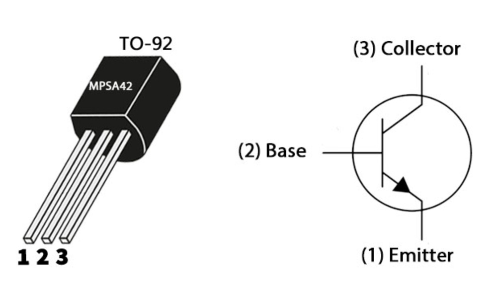
| Número PIN | Nombre del pin | Descripción de la función |
|---|---|---|
| 1 | E (Emisor) | Emitter, connected to ground or current output terminal |
| 2 | B (Base) | Base, controls the switch conduction |
| 3 | C (Coleccionista) | Collector, connected to load or power supply |
When you get your MPSA42 transistor, you’ll notice it’s marked either as “MPSA42” or just “A42” on the flat side of its black plastic casing. It handles high voltages (up to 300V), but only around 500mA current, so don’t try powering big loads with it. Also, pay attention to the pin order—it’s E-B-C, same as 2N3904 but different from the common BC547’s C-B-E arrangement, easy to mix up. And if using it as a switch, add a few kilo-ohm resistor on the base to avoid damaging it with excessive current.
MPSA42 Equivalent Transistor


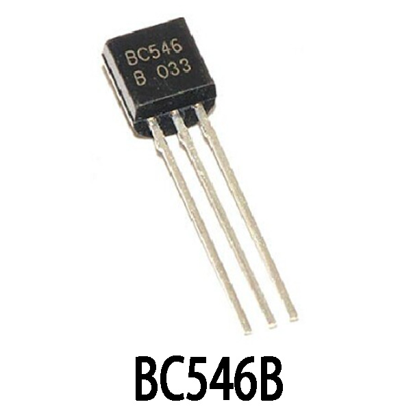
| Parámetro | MPSA42 | 2N5551 | KSP42 | BC546B |
|---|---|---|---|---|
| Tipo | NPN | NPN | NPN | NPN |
| Max Voltage VDirector ejecutivo | 300V | 160 V | 300V | 65 V |
| Max Current Ido | 500 mA | 600 mA | 500 mA | 100 mA |
| Power Dissipation (Ptot) | 625mW | 625mW | 625mW | 500 mW |
| Gain hFE | 40–200 | 75–300 | 40–200 | 200–450 |
| FT (MHz) | 50 | 100 | 50 | 150 |
| Paquete | TO-92 | TO-92 | TO-92 | TO-92 |
If you’re out of MPSA42, the KSP42 is basically identical—just look for that marking. For circuits below 150V, the 2N5551 works great with higher current capacity (600mA) and better gain, especially good for audio and signal amplification. Avoid the BC546B unless you’re just amplifying small signals, since it can’t handle higher voltages. Always double-check pin order in the datasheet (usually E-B-C) to avoid mix-ups.
MPSA42 Amplifier Circuit Example

This diagram shows a classic common-emitter amplifier using an MPSA42. The base gets its bias through a resistor from VBB, the collector connects to VCC through RC, and the emitter goes straight to ground. You’ll see this setup a lot in signal amplification. The current directions—IB, IC, and IE—are clearly marked, so it’s easy to tell it’s designed for amplification. MPSA42 is an NPN transistor that handles high voltage and low current, perfect for signal or audio amplification. This kind of circuit is exactly where it shines.
MPSA42 Switching Circuit Schematic
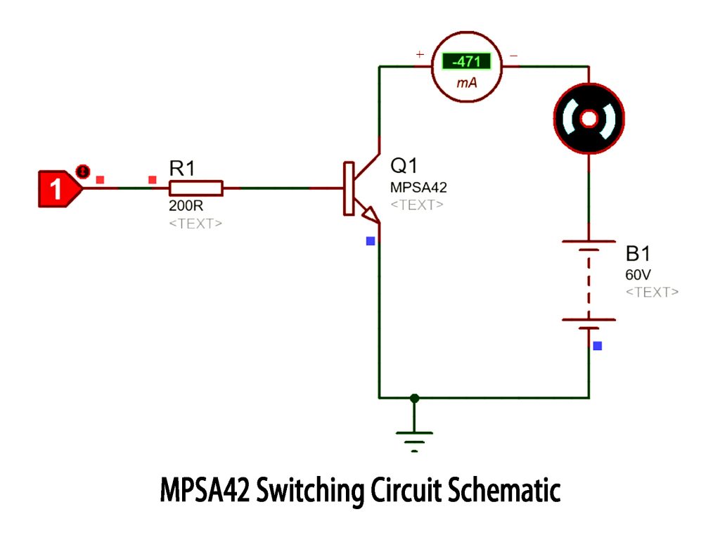
‘This one’s a pretty typical switching setup using an MPSA42. The transistor acts like a switch—collector connects to a load (maybe a motor or buzzer), and the emitter goes to ground. The load’s tied to a 60V source, classic high-side switching. There’s a 200Ω resistor at the base to control it. Once the signal comes in, the transistor turns on and you get around 471mA flowing—means the load’s working just fine. The title “mpsa42 switching circuit schematic” fits the circuit perfectly.
MPSA42 High Voltage Amplifier Usage
The MPSA42 transistor is your go-to choice for high-voltage amplification—it comfortably handles up to around 300V. Say you’ve got an audio or PWM signal in the 100-200V range; you’d typically set up a common-emitter amplifier. You feed a small signal (just a few volts from something like an MCU output) through a resistor into the base, then run a resistor from the collector up to a high voltage supply (like 150V). This setup boosts your signal to tens or even hundreds of volts, perfect for driving high-voltage relays, audio front-ends, or industrial scan circuits. Just keep an eye on its voltage limit (300V max) and try not to push its current too close to its 500mA limit—it heats up fast under heavy load.
Más como esto

AUIRGDC0250AKMA1
Tecnologías Infineon
IRGB4062DPBF
Rectificador internacional
FGPF4533RDTU
onsemi
SFGH30N60LSDTU
onsemi
SFGH25N120FTDS
onsemi
SFGH50N3
onsemi
FGA50T65SHD-01
onsemi
SHGTG40N60A4
onsemi
AFGHL40T120RH
onsemi
AFGHL25T120RL
onsemi
AFGHL25T120RH
onsemi
AFGHL40T120RL
onsemi
Añadir también al carrito
ISO3116I65HPSA1
Tecnologías Infineon

2SC5086-Y,LF
Toshiba Semiconductores y almacenamiento
NXH80B120MNQ0SNG
onsemi

IPW60R120P7
Tecnologías Infineon

MJE13007G
onsemi
CS3P-40P
Corporación Central de Semiconductores

BLP10H603Z
Ampleon USA Inc.

S8070WTP
Littelfuse Inc.

FSBB20CH60
onsemi

TT280N18SOFHPSA1
Tecnologías Infineon

PMP4201G135
NXP Estados Unidos Inc.
IKW40N120CS6XKSA1
Tecnologías Infineon
Productos relacionados
AUIRGDC0250AKMA1
Tecnologías Infineon
IRGB4062DPBF
Rectificador internacional
FGPF4533RDTU
onsemi
SFGH30N60LSDTU
onsemi
SFGH25N120FTDS
onsemi
SFGH50N3
onsemi
FGA50T65SHD-01
onsemi
SHGTG40N60A4
onsemi
AFGHL40T120RH
onsemi
AFGHL25T120RL
onsemi
AFGHL25T120RH
onsemi
AFGHL40T120RL
onsemi
STG30H65FBD7
STMicroelectrónica
IGC193T120T12RMAX7SA1
Tecnologías Infineon
SIGC28T65EX1SA1
Tecnologías Infineon
SIGC19T60SEX1SA1
Tecnologías Infineon
SIGC28T60SEX1SA2
Tecnologías Infineon
SIGC15T60SEX7SA1
Tecnologías Infineon
IGC08T65U12QX7SA1
Tecnologías Infineon
AODH6600
Alfa y Omega Semiconductor Inc.
AFGY120T65SPD-B4
onsemi
NCG100F475NF120
onsemi
NCG225L75NF8M1
onsemi
LGD8201TH
IXYS

LGB8204ATH
IXYS
LGB8207ATH
IXYS
AUXTMGPS4070D2
Tecnologías Infineon
AUXTMGPS4070D1
Tecnologías Infineon
NGTD13T120F2WP
onsemi
PCFG40T65SQF
onsemi
Envíe RFQ, le responderemos de inmediato.
