
STM32F030F4P6 pinout, Arduino, datasheet
- CoreProcessor: ARM® Cortex®-M0
- Core Size: 32-Bit Single-Core
- Peripherals: DMA, POR, PWM, WDT
- Package: 20-TSSOP (0.173, 4.40mm Width)


FREE delivery for orders over HK$250.00

Quick response, quick quotaton

Flash shipment,no worries after sales

Original channel,guarantee of the authentic products
78. STM32F030F4P6 Blink LED through ST LINK V2 using STM32 CubeIDE
STM32F030F4P6
The STM32F030F4P6 is a low-power microcontroller with a 32-bit ARM Cortex-M0 core. It runs at up to 48 MHz, offering good performance without draining too much power. With 16 KB of flash memory and 4 KB of SRAM, it has enough space for your code and data. There are 32 general-purpose I/O pins that can be used for things like GPIO, PWM, and ADC, and it supports communication through UART, SPI, I2C, and CAN. It also has a 12-bit ADC for precise analog-to-digital conversion and several timers for tasks like motor control. This microcontroller is great for space-constrained, battery-powered projects with a wide voltage range of 2.4V to 3.6V.
STM32F030F4P6 Pinout
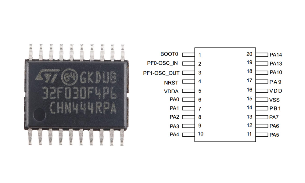
| Pin Number | Pin Name | Function |
|---|---|---|
| 1 | BOOT0 | Boot mode selection pin (used to select bootloader mode) |
| 2 | PF0-OSC_IN | Oscillator input pin |
| 3 | PF1-OSC_OUT | Oscillator output pin |
| 4 | NRST | External reset pin |
| 5 | VDDA | Analog power supply |
| 6 | PA0 | General-purpose I/O or ADC input |
| 7 | PA1 | General-purpose I/O or ADC input |
| 8 | PA2 | General-purpose I/O or UART TX pin |
| 9 | PA3 | General-purpose I/O or UART RX pin |
| 10 | PA4 | General-purpose I/O or SPI MOSI |
| 11 | PA5 | General-purpose I/O or SPI SCK |
| 12 | PA6 | General-purpose I/O or SPI MISO |
| 13 | PA7 | General-purpose I/O |
| 14 | PA8 | General-purpose I/O or I2C SCL |
| 15 | PA9 | General-purpose I/O or I2C SDA |
| 16 | VDD | Digital power supply |
| 17 | PA10 | General-purpose I/O or SPI CS |
| 18 | PA13 | Debug pin (SWDIO) |
| 19 | PA14 | Debug pin (SWCLK) |
| 20 | PB1 | General-purpose I/O |
The BOOT0 pin is used to choose the boot mode for the STM32F030F4P6. If it’s pulled high during reset, the microcontroller enters bootloader mode (to load code via UART or USB). Otherwise, it boots from Flash memory. PF0 and PF1 are for connecting an external clock if you’re using one. The NRST pin is for resetting the microcontroller, usually connected to external reset circuitry. VDDA powers the analog section of the microcontroller, so it needs to be supplied with a voltage, typically 3.3V. PAx pins are general-purpose and can be set up for different functions like analog inputs (ADC), UART, SPI, or I2C. For UART, PA2 and PA3 are used, while PA4, PA5, and PA6 are for SPI. PA8 and PA9 are used for I2C. PB1 is another general-purpose pin for various uses.
STM32F030F4P6 Equivalent STM32 Chip
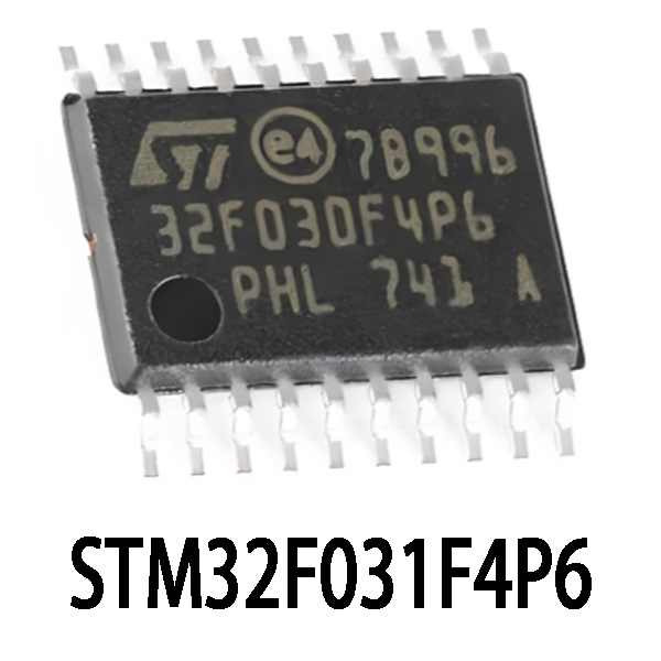
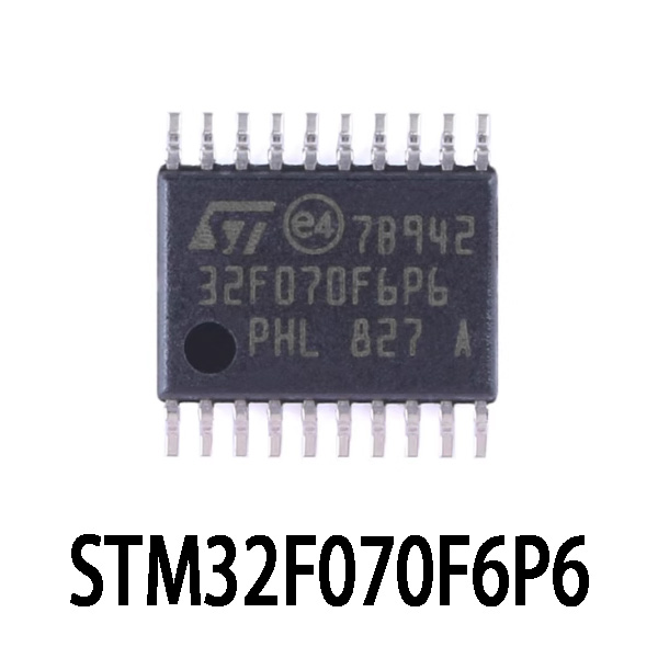
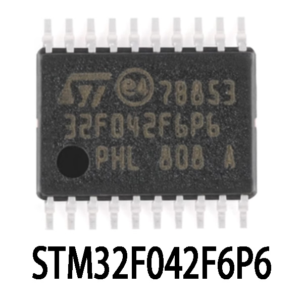
| Parameter | STM32F030F4P6 | STM32F031F4P6 | STM32F042F6P6 | STM32F070F6P6 |
|---|---|---|---|---|
| Core | Cortex-M0 | Cortex-M0 | Cortex-M0 | Cortex-M0 |
| Flash Memory | 16 KB | 16 KB | 32 KB | 32 KB |
| SRAM | 4 KB | 4 KB | 6~8 KB | 4 KB |
| Max Frequency | 48 MHz | 48 MHz | 48 MHz | 48 MHz |
| ADC Channels | 12-bit, 11 channels | 12-bit, 11 channels | 12-bit, 10 channels | 12-bit, 10 channels |
| Timer | Advanced + 7 General | Advanced + 7 General | Advanced + 7 General | Advanced + 7 General |
| I/O Interface | I²C×2, SPI×2, USART×6 | I²C×2, SPI×2, USART×6 | I²C×2, SPI×2, USART×6, USB | I²C×2, SPI×2, USART×6, USB |
| Voltage Range | 2.4~3.6 V | 2.4~3.6 V | 2.4~3.6 V | 2.4~3.6 V |
| Operating Temperature | -40~85°C | -40~85°C | -40~85°C | -40~85°C |
| Package | 20-TSSOP | 20-TSSOP | 20-TSSOP | 20-TSSOP |
When choosing a replacement chip, STM32F031F4P6 is your safest bet—it’s identical to your current chip in terms of pins, memory, and frequency, so it drops right in without any hassle.
If you’re looking to boost functionality or add more room for future upgrades, check out STM32F042F6P6 or STM32F070F6P6. These have a bigger flash memory of 32KB, and STM32F042F6P6 even packs in a USB interface and extra SRAM (6~8KB). They’re great if your project might need USB communication or more memory. Just remember, the USB feature uses pins PA11 and PA12, so double-check your existing circuit doesn’t already use these pins to avoid conflicts or extra work tweaking your code.
STM32F030F4P6 Minimum System Circuit
This circuit diagram shows the basic setup for the STM32F030F4P6 microcontroller. It’s powered by a 3.3V supply connected to the VDD pin, and the GND pin connects to ground. The reset button lets you manually reset the microcontroller by pressing it, while the BOOT0 pin controls the boot mode, which you can adjust with a button. If needed, external oscillators can be connected to the PF0 (OSC_IN) and PF1 (OSC_OUT) pins. The capacitors (C1, C2, C3) help filter and stabilize the power supply and reset functions. This setup gives you everything to power, reset, and configure the microcontroller for initial use.
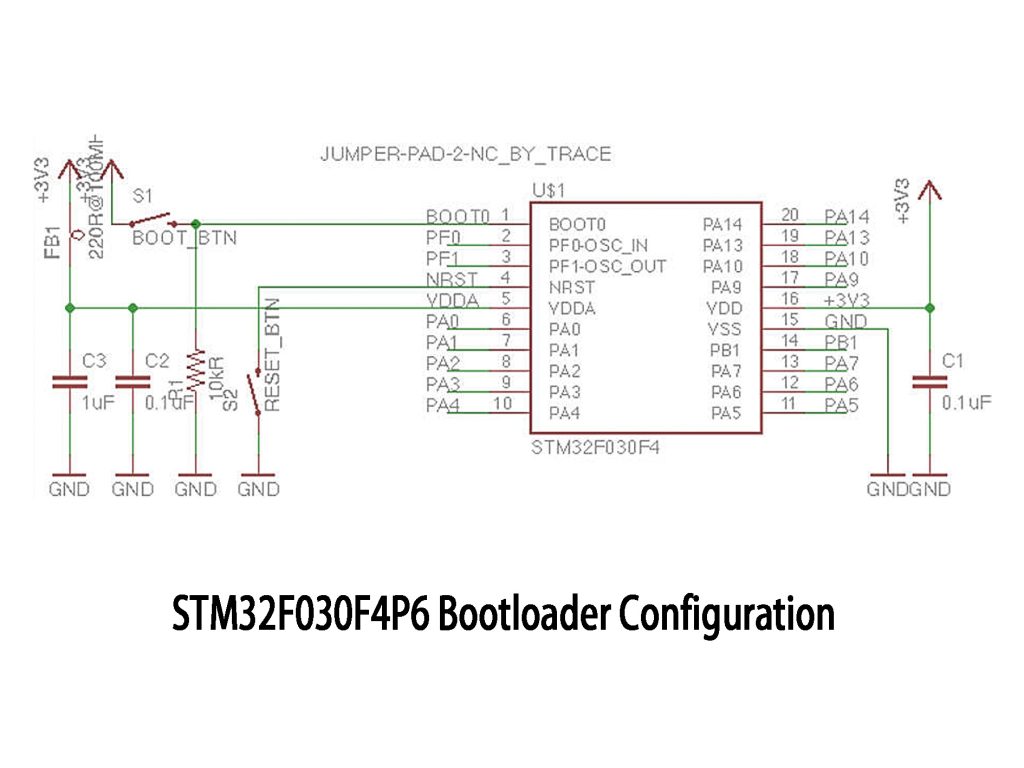
STM32F030F4P6 Bootloader Configuration
The STM32F030F4P6 has a built-in bootloader that allows you to load firmware without needing a programmer. To use the bootloader, you need to configure the BOOT0 pin to High and BOOT1 to Low during reset. This will make the microcontroller boot from its system memory, where the bootloader resides. Once in bootloader mode, you can use USART, USB, or other interfaces to send firmware to the microcontroller. Tools like STM32CubeProgrammer let you flash the firmware over a serial connection. Just make sure to switch BOOT0 back to Low after booting to run your application.
STM32F030F4P6 Development Board Example
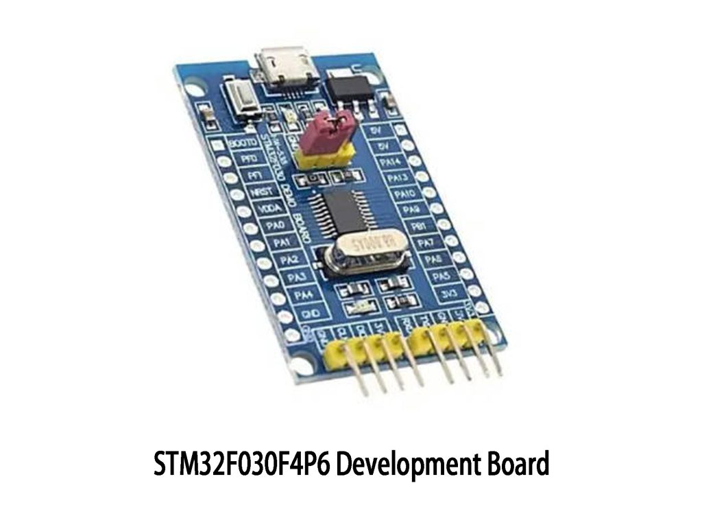
The STM32F030F4P6 development board is a great choice for low-power applications. It runs on an ARM Cortex-M0 core, providing up to 48 MHz of processing power, which is perfect for tasks like sensor interfacing, motor control, and basic communication. The board has a USB connector for easy programming and debugging. You’ll also find a variety of GPIO pins (PA0 to PA15, PB0 to PB15) for connecting sensors, motors, or LEDs. It can be powered via USB or a 5V input pin, giving you flexible options. The built-in crystal oscillator ensures accurate timing. You can use STM32CubeIDE or STM32CubeMX for development and code generation. This board is ideal for IoT, embedded systems, or prototyping.
More Like This

8N3SV76LC-0063CDI8
Renesas Electronics America Inc

8N3SV76LC-0063CDI
Renesas Electronics America Inc

8N3SV76LC-0062CDI8
Renesas Electronics America Inc

8N3SV76LC-0062CDI
Renesas Electronics America Inc

8N3SV76LC-0061CDI8
Renesas Electronics America Inc

8N3SV76LC-0061CDI
Renesas Electronics America Inc

8N3SV76LC-0060CDI8
Renesas Electronics America Inc

8N3SV76LC-0060CDI
Renesas Electronics America Inc

8N3SV76LC-0059CDI8
Renesas Electronics America Inc

8N3SV76LC-0059CDI
Renesas Electronics America Inc

8N3SV76LC-0058CDI8
Renesas Electronics America Inc

8N3SV76LC-0058CDI
Renesas Electronics America Inc
Also Add to Cart

MD7550H
Shanghai Mingda Microelectronics

MP8847GD-Z
Monolithic Power Systems Inc.

M2S050-VF400I
Microchip Technology

72V241L20PF8
Renesas Electronics America Inc

AD544LH
Analog Devices Inc.

CDP1802CD
Harris Corporation

SSM3525BCBZRL
Analog Devices Inc.
MIMX8MN3CUCIZAA
NXP USA Inc.

MCP131T-315E/LB
Microchip Technology
5ASXFB5H4F40C4G
Intel

DM3730CBC
Texas Instruments

STM32L151C8T6A
STMicroelectronics
Related Products
8N3SV76LC-0063CDI8
Renesas Electronics America Inc
8N3SV76LC-0063CDI
Renesas Electronics America Inc
8N3SV76LC-0062CDI8
Renesas Electronics America Inc
8N3SV76LC-0062CDI
Renesas Electronics America Inc
8N3SV76LC-0061CDI8
Renesas Electronics America Inc
8N3SV76LC-0061CDI
Renesas Electronics America Inc
8N3SV76LC-0060CDI8
Renesas Electronics America Inc
8N3SV76LC-0060CDI
Renesas Electronics America Inc
8N3SV76LC-0059CDI8
Renesas Electronics America Inc
8N3SV76LC-0059CDI
Renesas Electronics America Inc
8N3SV76LC-0058CDI8
Renesas Electronics America Inc
8N3SV76LC-0058CDI
Renesas Electronics America Inc

8N3SV76LC-0057CDI8
Renesas Electronics America Inc

8N3SV76LC-0057CDI
Renesas Electronics America Inc

8N3SV76LC-0056CDI8
Renesas Electronics America Inc

8N3SV76LC-0056CDI
Renesas Electronics America Inc

8N3SV76LC-0055CDI8
Renesas Electronics America Inc

8N3SV76LC-0055CDI
Renesas Electronics America Inc

8N3SV76LC-0054CDI8
Renesas Electronics America Inc

8N3SV76LC-0054CDI
Renesas Electronics America Inc

8N3SV76LC-0053CDI8
Renesas Electronics America Inc

8N3SV76LC-0053CDI
Renesas Electronics America Inc

8N3SV76LC-0052CDI8
Renesas Electronics America Inc

8N3SV76LC-0052CDI
Renesas Electronics America Inc

8N3SV76LC-0051CDI8
Renesas Electronics America Inc

8N3SV76LC-0051CDI
Renesas Electronics America Inc

8N3SV76LC-0073CDI
Renesas Electronics America Inc

8N3SV76LC-0072CDI8
Renesas Electronics America Inc

8N3SV76LC-0072CDI
Renesas Electronics America Inc

8N3SV76LC-0071CDI8
Renesas Electronics America Inc
Please send RFQ , we will respond immediately.
