
STM32F405RGT6 datasheet & price | development board
- Procesador central: ARM® Cortex®-M4
- Tamaño del núcleo: Núcleo único de 32 bits
- Periféricos: Detección/reinicio de caída de tensión, DMA, I²S, LCD, POR, PWM, WDT
- Paquete: 64-LQFP


Envío GRATUITO para pedidos superiores a HK$250.00

Respuesta rápida, cotización rápida.

Envío rápido, sin preocupaciones posventa.

Canal original, garantía de los productos auténticos.
STM32F405RGT6 Embedded-Microcontrollers IC MCU 32BIT 1MB FLASH 64LQFP
Stm32f405rgt6
Let’s break down the key features of this microcontroller. It’s built on the ARM Cortex-M4 core, running at up to 168 MHz, which makes it perfect for applications that need fast real-time processing. You’ve got 512KB of flash storage and 192KB of SRAM, so there’s plenty of room for your program and data.
It has up to 82 GPIO pins, giving you a lot of flexibility for connecting sensors, actuators, and other devices. The microcontroller supports a variety of communication interfaces like USART, SPI, I2C, CAN, and USB 2.0, making it versatile for different setups.
For precision, it includes a 12-bit ADC, DAC, and PWM outputs, great for signal generation and control. Plus, it has hardware acceleration for things like multiplication, division, and CRC checks, boosting its performance. With low-power modes, it’s also well-suited for battery-powered applications like portable devices and IoT projects.
This MCU is perfect for everything from industrial control to audio processing and embedded systems.
Stm32f405rgt6 Pinout

| Alfiler | Nombre | Descripción |
|---|---|---|
| 1 | VBAT | Battery input for RTC |
| 2 | PC13 | GPIO/RTC |
| 3 | PC14 | GPIO/RTC |
| 4 | PC15 | GPIO/RTC |
| 5 | PH0 | High-speed external clock |
| 6 | PH1 | High-speed external clock |
| 7 | NRST | Reset |
| 8 | PC0 | GPIO/ADC12_IN10 |
| 9 | PC1 | GPIO/ADC12_IN11 |
| 10 | PC2 | GPIO/ADC12_IN12 |
| 11 | PC3 | GPIO/ADC12_IN13 |
| 12 | VSSA | Analog ground |
| 13 | VDDA | Analog power |
| 14 | PA0_WKUP | GPIO/ADC12_IN0 |
| 15 | PA0 | GPIO/ADC12_IN0 |
| 16 | PA2 | GPIO/ADC12_IN2 |
| 17 | PA3 | GPIO/ADC12_IN3 |
| 18 | VSS | Suelo |
| 19 | VDD | Digital power |
| 20 | PA4 | GPIO/ADC12_IN4 |
| 21 | PA5 | GPIO/ADC12_IN5 |
| 22 | PA6 | GPIO/ADC12_IN6 |
| 23 | PA7 | GPIO/ADC12_IN7 |
| 24 | PC4 | GPIO/ADC12_IN14 |
| 25 | PC5 | GPIO/ADC12_IN15 |
| 26 | PB0 | GPIO/ADC12_IN8 |
| 27 | PB1 | GPIO/ADC12_IN9 |
| 28 | PB2 | GPIO |
| 29 | PB10 | GPIO/I2C2_SCL |
| 30 | PB11 | GPIO/I2C2_SDA |
| 31 | VCAP_1 | Capacitor for internal regulator |
| 32 | VDD | Digital power |
| 33 | PB12 | GPIO/SPI2_MISO |
| 34 | PB13 | GPIO/SPI2_MOSI |
| 35 | PB14 | GPIO/SPI2_SCK |
| 36 | PB15 | GPIO/SPI2_NSS |
| 37 | PC6 | GPIO/USART6_TX |
| 38 | PC7 | GPIO/USART6_RX |
| 39 | PC8 | GPIO |
| 40 | PC9 | GPIO |
| 41 | PA8 | GPIO/USART1_TX |
| 42 | PA9 | GPIO/USART1_RX |
| 43 | PA10 | GPIO/USART1_CK |
| 44 | PA11 | GPIO/USART1_CTS |
| 45 | PA12 | GPIO/USART1_RTS |
| 46 | PA13 | GPIO/SWDIO |
| 47 | VCAP_2 | Capacitor for internal regulator |
| 48 | VDD | Digital power |
| 49 | PA14 | GPIO/SWCLK |
| 50 | PA15 | GPIO |
| 51 | PC10 | GPIO/UART4_TX |
| 52 | PC11 | GPIO/UART4_RX |
| 53 | PC12 | GPIO/UART5_TX |
| 54 | PD2 | GPIO/UART5_RX |
| 55 | PB3 | GPIO |
| 56 | PB4 | GPIO |
| 57 | PB5 | GPIO |
| 58 | PB6 | GPIO |
| 59 | PB7 | GPIO |
| 60 | BOOT0 | Boot configuration pin |
| 61 | PB8 | GPIO |
| 62 | PB9 | GPIO |
| 63 | VSS | Suelo |
| 64 | VDD | Digital power |
Here’s what you need to know when using the STM32F405RGT6 microcontroller. First, make sure you connect the VDD and VSS pins to your power supply (usually 3.3V) and ground (GND). These connections are crucial for the MCU to function properly.
The GPIO pins on this MCU are highly flexible. You can configure them for inputs, outputs, or alternate functions like SPI, I2C, USART, and PWM—ideal for controlling motors or interacting with sensors and displays.
For analog signal processing, the pins from PA0 to PA7, PB0 to PB7, and PC0 to PC5 support ADC input, which is great for reading analog signals. Additionally, you can generate PWM signals through various pins for applications like motor control.
It also supports multiple communication protocols like USART, SPI, and I2C for easy data exchange with other devices. For debugging, you can use the PA13 and PA14 pins with an external debugger.
Finally, with a temperature range of -40°C to +85°C and various low-power modes, the STM32F405RGT6 is perfect for both industrial and battery-powered applications.
Stm32f405rgt6 Equivalent Stm32 Chip
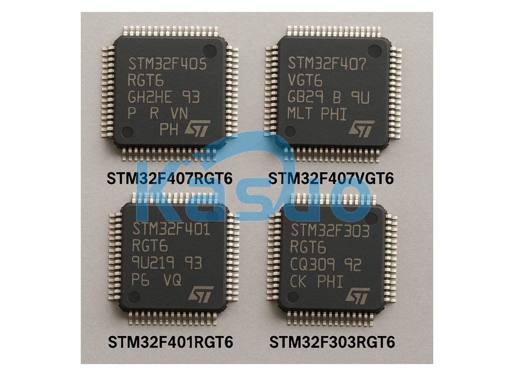
| Parámetro | STM32F405RGT6 | STM32F407VGT6 | STM32F401RGT6 | STM32F303RGT6 |
|---|---|---|---|---|
| Core Architecture | ARM Cortex-M4 | ARM Cortex-M4 | ARM Cortex-M4 | ARM Cortex-M4 |
| Maximum Frequency | 168 MHz | 168 MHz | 84 MHz | 72 MHz |
| Flash Memory | 512 KB | 512 KB | 512 KB | 256 KB |
| RAM | 192 KB | 192 KB | 96 KB | 40 KB |
| Pin Count | 100 pins (LQFP) | 100 pins (LQFP) | 100 pins (LQFP) | 64 pins (LQFP) |
| Maximum Drain Voltage (Vds) | 3.6V | 3.6V | 3.6V | 3.6V |
| Operating Temperature Range | -40°C a 85°C | -40°C a 85°C | -40°C a 85°C | -40°C a 85°C |
| External Interfaces | GPIO, UART, SPI, I2C, CAN, USB | GPIO, UART, SPI, I2C, CAN, USB | GPIO, UART, SPI, I2C, CAN, USB | GPIO, UART, SPI, I2C, CAN |
| Functionality | Low Power | Low Power | Low Power | Low Power |
When choosing a replacement for the STM32F405RGT6, here are a few things to keep in mind. Both the STM32F405RGT6 and STM32F407VGT6 use the ARM Cortex-M4 core, running at up to 168 MHz, making them great for high-performance applications. On the other hand, the STM32F401RGT6 is also Cortex-M4 but runs at 84 MHz, which is perfect for less demanding tasks.
If you need something with lower power consumption or for simpler control tasks, the STM32F303RGT6 is a good option, though it has a lower clock speed of 72 MHz.
When it comes to memory, the STM32F405RGT6 and STM32F407VGT6 offer 512 KB of Flash and 192 KB of SRAM, making them ideal for applications needing more storage. Meanwhile, the STM32F401RGT6 and STM32F303RGT6 provide smaller memory options, with the STM32F303RGT6 offering 256 KB Flash and 40 KB SRAM.
All models support essential peripherals like UART, SPI, I2C, and CAN, with the STM32F303RGT6 being more suited for basic control tasks. They also offer low-power operation and can handle temperatures from -40°C to 85°C, making them adaptable for industrial and battery-powered applications.
Stm32f405rgt6 Development Board Circuit
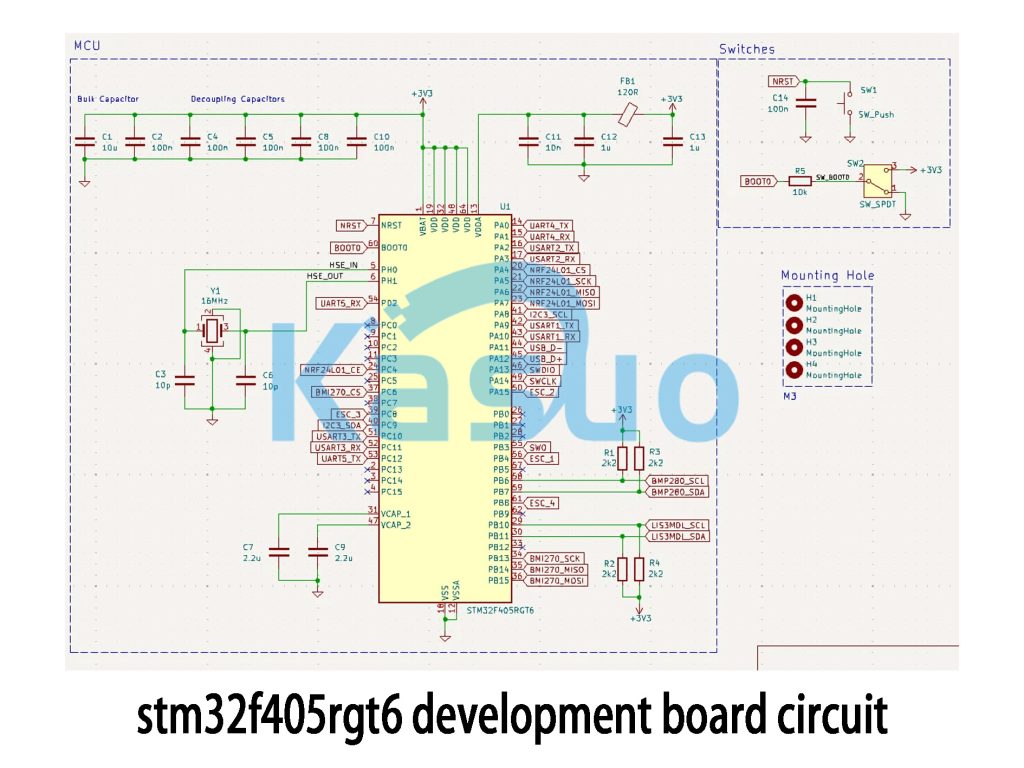
Let’s break down the key parts of this STM32F405RGT6 development board circuit. First, the power section ensures stable 3.3V for the microcontroller, filtered through capacitors (C1, C2) to reduce noise and keep the system running smoothly.
The clock section uses an external 12MHz crystal (Y1), connected through the HSE pins, to provide the main clock source, ensuring precise timing for your applications.
For communication, the board supports several interfaces like USART for serial communication, SPI for connecting external sensors (like BMP280, BME270), and I2C for other devices. There are also GPIO pins for switches and peripherals.
The board includes buttons (SW1, SW2) for user input and debugging, while the SWD interface allows you to program and debug the microcontroller easily.
A solid power design, stable clock source, and correct peripheral connections are key to ensuring the development board works reliably. Proper filtering and decoupling capacitors help with noise reduction, while the reset circuit ensures the board starts properly each time.
Stm32f405rgt6 Bootloader Configuration
When working with the STM32F405RGT6 microcontroller, configuring the Bootloader is crucial because it determines how the device loads the firmware when powered on. This process mainly involves the BOOT0 and BOOT1 pins.
Here’s how it works:
-
BOOT0 Pin:
-
When BOOT0 = 0, the microcontroller starts from Flash memory (where your application is stored).
-
When BOOT0 = 1, it enters Bootloader mode, allowing you to load firmware via USART, USB, or CAN.
-
-
BOOT1 Pin: For the STM32F405RGT6, BOOT1 is fixed at 0, so only BOOT0 controls the startup mode.
To enter Bootloader mode, you can pull BOOT0 high (connect to 3.3V) manually or use an external button. If you want to use the USB Bootloader, ensure BOOT0 is high, and connect it to the USB host.
You can also use STM32CubeProgrammer to upload your firmware via USB, USART, or CAN. Just set BOOT0 high, connect the device to your PC, and follow the steps in STM32CubeProgrammer to load the firmware into Flash memory.
Stm32f405rgt6 Clock and Peripheral Setup
When configuring the STM32F405RGT6’s clock system, it’s important to set up the right clock sources for your application. You have two main options: the High-Speed External (HSE) crystal or the High-Speed Internal (HSI) oscillator. Typically, you’ll use the HSE with an external 12 MHz crystal for better stability, but the HSI can be used if you don’t need an external oscillator.
To boost performance, you can use the Phase-Locked Loop (PLL) to multiply the HSE or HSI frequency. For example, by using a PLL with a 12 MHz HSE, you can achieve a system clock (SYSCLK) of 168 MHz, which is ideal for high-performance tasks.
Once your system clock is set, don’t forget to configure the clocks for each peripheral, like GPIO, USART, SPI, or I2C, to make sure they work properly. You can enable these clocks through the RCC registers, which control the clocking for all peripherals. Be sure to check that the peripherals are getting the right clock speeds for their tasks.
Stm32f405rgt6 Usb Interface Example
When working with the STM32F405RGT6 microcontroller, the USB interface is key for connecting to external devices. It supports USB 2.0 Full-Speed (12Mbps) and can switch between Device, Host, and OTG modes. This makes it really versatile for applications like USB keyboards, mice, and storage devices.
To set up the USB device interface, connect the USB Data Minus (PA11) and Data Plus (PA12) pins to the corresponding USB data lines. You’ll also need to connect the VBUS pin to the USB host’s power and ground the GND pin. After that, ensure the USB OTG clock is enabled and set up the appropriate USB class, like the CDC (Virtual COM Port) class, for communication.
Once the hardware is set up, you can use tools like STM32CubeMX to configure the USB device driver and set up the communication. After everything is connected, your PC should recognize the STM32 as a new virtual COM port, allowing you to send and receive data with tools like Tera Term or PuTTY.
Más como esto

96MPC4-2.0F8-5K7T
Corporación Advantech
96MP2DM-22GF8-4M4T
Corporación Advantech
96MP2DM-21F6-4M4T
Corporación Advantech
96MP2DD-21FA-2M7T
Corporación Advantech
96MP2DD-18F8-2M7T
Corporación Advantech

ATSAMA5D27B-CU
Tecnología de microchip

ATSAMA5D26B-CU
Tecnología de microchip

ATSAMA5D24B-CU
Tecnología de microchip

ATSAMA5D22B-CU
Tecnología de microchip

ATSAMA5D21B-CU
Tecnología de microchip
AT80573QJ0806M
Corporación Advantech
AT80573QJ0536M
Corporación Advantech
Añadir también al carrito

CYPD5225-96BZXI
Corporación Cypress Semiconductor

74LVT16373ADGG,118
Nexperia USA Inc.
BCM3382DIFEBG
Broadcom Limited

OMAP3525DCBBA
Texas Instruments

ADSP-BF531SBSTZC43
Dispositivos analógicos Inc.
74LVC1G74DP
Nexperia USA Inc.

TP3420AN308
Texas Instruments
;;2.jpg "L78M12CDT-TR")
L78M12CDT-TR
STMicroelectrónica

ISL28291FUZ-T7
Renesas Electronics America Inc

SN65LVDM22PW
Texas Instruments

74AHC244PW
Nexperia

TCA9416DTMR
Texas Instruments
Productos relacionados
96MPC4-2.0F8-5K7T
Corporación Advantech
96MP2DM-22GF8-4M4T
Corporación Advantech
96MP2DM-21F6-4M4T
Corporación Advantech
96MP2DD-21FA-2M7T
Corporación Advantech
96MP2DD-18F8-2M7T
Corporación Advantech
ATSAMA5D27B-CU
Tecnología de microchip
ATSAMA5D26B-CU
Tecnología de microchip
ATSAMA5D24B-CU
Tecnología de microchip
ATSAMA5D22B-CU
Tecnología de microchip
ATSAMA5D21B-CU
Tecnología de microchip
AT80573QJ0806M
Corporación Advantech
AT80573QJ0536M
Corporación Advantech
S6100PHC-2
MaxLinear, Inc.
XLS616XD1200-21
Broadcom Limited
XLS616XD1000-21
Broadcom Limited
XLS416XD1000-21
Broadcom Limited
XLS416WD0800-21
Broadcom Limited
XLS408XD1000-21
Broadcom Limited
XLS408XD1000-11
Broadcom Limited
XLS408WD1000-11
Broadcom Limited
XLS208XD1000-11
Broadcom Limited
XLS208XD0750-11
Broadcom Limited
XLS208WD0750-11
Broadcom Limited
XLS204XD0900-11
Broadcom Limited
XLS204XD0750-11
Broadcom Limited
XLS204XD0600-11
Broadcom Limited
XLS108XD0750-11
Broadcom Limited
XLS104XD0750-11
Broadcom Limited
XLS104XD0500-11
Broadcom Limited
XLS018XD0750-11
Broadcom Limited
Envíe RFQ, le responderemos de inmediato.
