What is a Band Stop Filter? A Beginner’s Guide to Understanding the Circuit
Author:admin Date: 2025-06-26 07:46 Views:257
Band Pass Filter and Band Stop Filter Explained
Introduction
UN band stop filter is a type of filter designed to block or significantly attenuate frequencies within a specific range, which is the stop band, while allowing the other frequencies outside the band to pass through.
If you have come across a band pass filter, this is the exact opposite, which allows a specific band of frequencies to pass while rejecting those outside the band.
Such a type of filter comes with multiple applications such as audio processing, communication systems, optical systems, and RF circuits. It all depends on the application and the frequency range to be blocked.
We look more into the band stop filter to give you an idea of what it is, how it works, types, and much more.
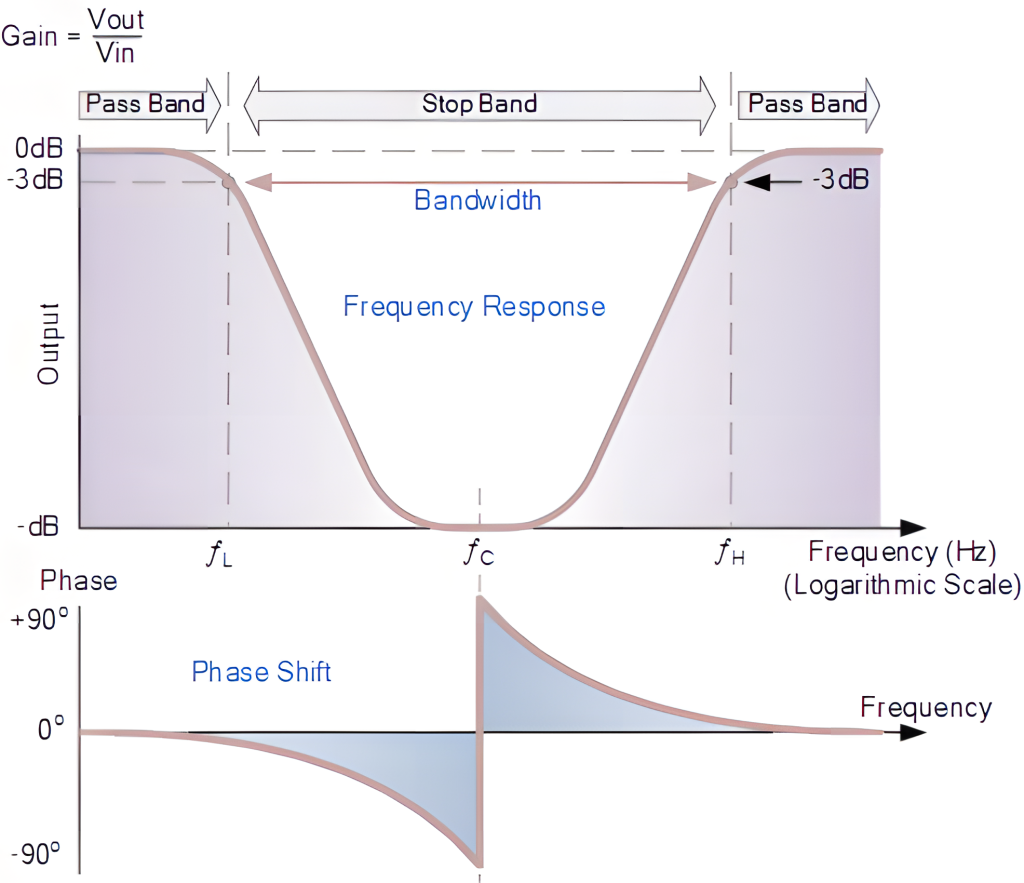
Band Stop Filter Characteristics
UN band stop filter circuit will exhibit several characteristics worth looking at. Below is what to expect when working with a band stop filter.
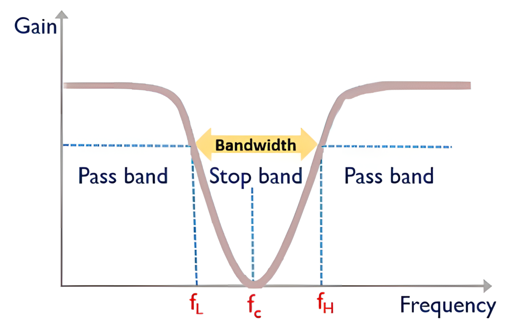
Center of Frequency
This is the frequency at which the band stop filter provides the maximum attenuation. It is also called the center of the notch.
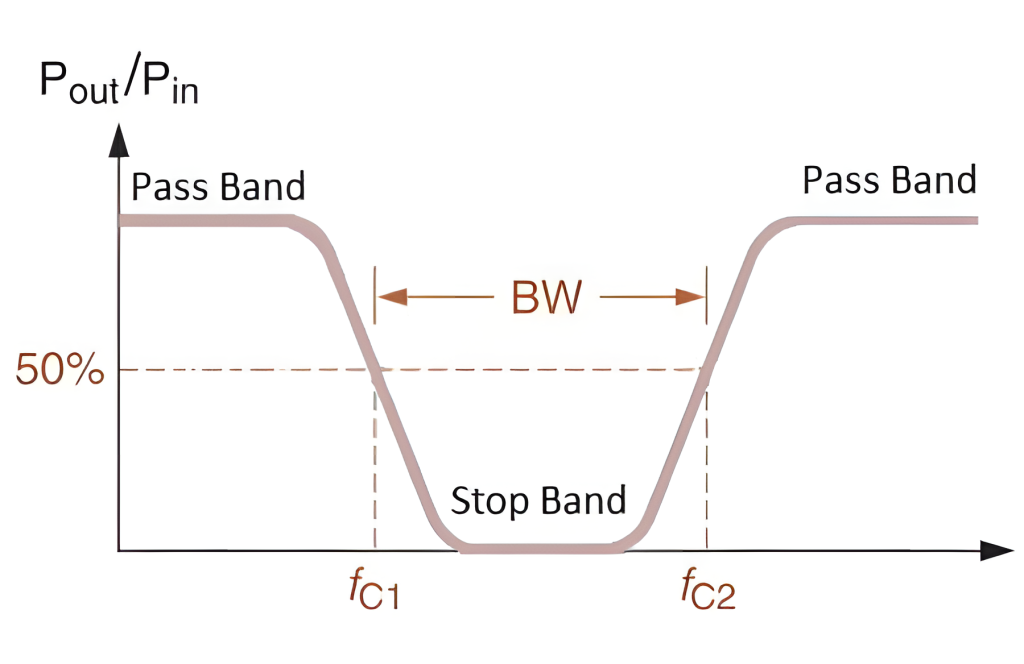
Bandwidth
The bandwidth of a passive or active band stop filter defines the frequency range around the center frequency that is attenuated. It is also referred to as the width of the stopband at a certain attenuation level.
Quality (Q) Factor
The Q factor is the measure of the filter’s sharpness or selectivity. Having a higher Q factor leads to a narrower bandwidth. A sharper notch means that the filter is more selective in how it attenuates at a specific frequency range.
Passband
As for the passband, these are the frequencies that the band stop filter allows to pass through it without any significant attenuation. These are the frequencies outside the filter’s stop band.
Roll-off Rate
This describes how quickly the band pass filter gain decreases as you move away from the center frequency and into the stop band. When you have a steeper roll-off, it leads to a faster attenuation.
Transfer Function
Le band stop filter transfer function is a mathematical expectation that describes the relationship between the input and output signals of a filter. It is used for designing and analyzing the band stop filter.
Types of Band Stop Filters
Before we can look into the band stop filter applications, first let us look at the types to have an idea of how each works. The main types include passive, active, and digital band stop filters.
Passive Band Stop Filters
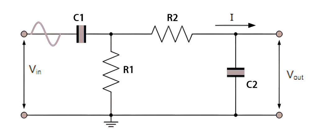
Le passive band stop filters rely on passive components such as resistors, inductors, and capacitors to operate.
A common example is a parallel RLC circuit in which the capacitor and inductor resonate the center frequency, which leads to high impedance and effectively blocks that frequency.
Passive filters come with a simpler design, which is also easy to implement. However, they are limited in terms of performance and tunability.
Active Band Stop Filters
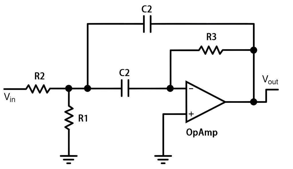
Active filters are different in that they incorporate active components. Such include operational amplifiers together with the passive components.
The op-amps used in the circuit offer better gain and impedance buffering. This allows for sharper roll-off characteristics and better control over the filter’s performance.
It is worth noting how active filters can provide higher Q factors and are easy to adjust or tune when necessary.
Digital Band Stop Filters
Such filters are implemented using digital signal processing techniques, which involve algorithms that run on dedicated DSP chips or microcontrollers. These filters are known for their high flexibility and programmability, which means dynamic adjustment of parameters such as bandwidth and center frequency is possible.
These filters also offer very sharp roll-offs and precise control over the filter characteristics, allowing them to surpass analog filters’ performance.
Notch Filter
This is a special type of the band stop filter known for having a very narrow stopband. It is designed to attenuate a very narrow frequency range while allowing other frequencies to pass with little to no attenuation.
Notch filters are commonly used to remove interference signals or unwanted tones.
Applications of Band Stop Filters
Whether it is the 1st or 2nd order band stop filter, it will have several applications. Such include:
- Audio systems use the band stop filters to remove the unwanted hum or noise from the audio signals. This includes the 50Hz or 60Hz hum from the power supplies in musical instrument amplifiers or public address systems.
- Medical equipment such as EEGs or ECGs uses this technology to eliminate power line interference, thus improving the signal quality and accuracy.
- This filter type can also reduce general noise to ensure signal clarity.
- Le band-stop active filter is handy for telecommunications applications. It includes interference rejection and channel separation, which are all important to ensure clear and reliable communication.
- Audio processing is also part of the many applications of the band stop filter. This is where features such as equalization can be achieved thanks to band stop filters. The filter can attenuate a specific frequency range, allowing for fine-tuning the sound to create the desired tonal balance.
Band Stop Filter Circuit Design
Whenever designing a band stop filter, you have to keep a couple of things in mind. Such include:
Center Frequency
This frequency should be chosen precisely so that the filter can reject that specific range.
Bandwidth
The bandwidth is key for determining the width of the stopband. So, when choosing the bandwidth, it can be narrow or wide. The wider bandwidth means it will attenuate a broader range of frequencies. The narrower bandwidth is more precise in its rejection.
Filter Order
You may encounter the first or second order as the filter order. This impacts the steepness of the filter’s roll-off, which is basically the rate at which the attenuation increases outside the stopband. Having a higher-order filter means a steeper roll-off, but it can be more complex and harder to implement.
Quality Factor
The design of a band-stop filter is not complete without the Q-factor. In this case, the Q-factor is proportional to the bandwidth. A higher Q factor means a narrower bandwidth and sharper attenuation. A lower Q factor leads to less sharp attenuation and wider bandwidth.
Component Tolerances
Components such as inductors, capacitors, and resistors have manufacturing tolerances, which can affect filter performance. To minimize the tolerance effects, use high-precision components.
Practical Considerations
Factors such as noise, PCB layout, and interference impact how the filter works. Design and layout the components carefully to minimize these effects. Before implementing the band-stop filter circuit diagram, you can try using simulation software to see how it works.
Conclusion
A band stop filter is vital for many applications, as we have seen above. You should now better understand how it works, the applications, and more features. Before implementing the band stop filter circuit diagram, you can try using simulation software to see how it works and make adjustments where necessary. The band stop filter can have more applications depending on how it is designed. You should take more time in the design stage to get desirable results. Always use simulation tools to better understand the circuit before implementing it. Also, keep in mind the design considerations to get the best results with the filter.
Veuillez envoyer une demande de devis, nous vous répondrons immédiatement.
Questions fréquemment posées
Is there a difference between a band stop filter and a notch filter?
A notch filter is considered a type of band stop filter that comes with a very narrow stop band. This type of filter can be ideal for removing a single unwanted frequency. Compared to the general band stop filter, it will be used for targeting a wider frequency range.
How best can you design a band stop filter circuit?
For this type of filter, start by choosing the desired stopband frequency range. You can use standard filter design equations with the right RLC or op-amp configurations. Tools such as MATLAB, LTspice, and Multisim can help you design, test, and tune the filter before implementing it.
Are band-stop filters common in digital electronics?
Yes. Digital band stop filters are used for real-time signal processing tasks. They are common in audio editing, embedded systems, and communication technologies.