Guide du débutant sur l'utilisation des portes logiques : fonctionnement des appareils numériques
Author:admin Date: 2025-05-29 08:04 Views:894
When designing digital circuits, you will likely come across many similar components, even if the circuits are different. One of those components is the logic gate. This is a common component that plays an important role in ensuring the circuit works as expected. With that in mind, what is a logic gate?
We discuss logic gates, their applications, how they work, and more. At least you will have a good understanding of how you can utilize the logic gates to get the best performance all the time.
What is a Logic Gate?
A logic gate is a fundamental building block for digital circuits. It performs logical operations depending on the number of binary inputs, resulting in a single binary output. Expect it to be built from the arrangement of diodes and transistors.
Logic gates vary in operations, with the common ones being AND, NOT, and OR. However, the operations can get complicated depending on the setup and desired output from the circuit.
Importance of Logic Gates
Un AND logic gate ou NAND logic gate is used in different circuits for several reasons. Here are some of them.
- Logic gates remain fundamental to all digital circuits. This means they are essential for various modern electronic devices to function correctly. This might include performing tasks such as making decisions, switching, data storage, and more.
- The logic gates are also key in implementing complex algorithms vital for logical operations. That is why you will come across them in applications that involve calculations, controlling data flow, and more.
- Expect better speed and efficiency when using logic gates for various applications. Modern electronics have fast data processing and transfer speeds because of this.
- Logic gates also make electronics consume minimal power, which is what many people would want when seeking electronics.
- Logic gates are the backbone of modern electronics. That is why they are found in integrated circuits, and they are constantly evolving to improve their performance.
Main Components of a Logic Gate
Logic gates are mostly made using diodes or transistors. However, other components, such as resistors, can also be used. Each component has a specific purpose: to make the logic gate work as expected based on the logic gate truth table.
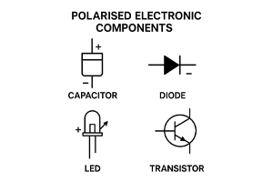
Transistors are mainly used in logic gates because they can act as electronic switches. They can easily turn on or off depending on the type of input signal. Right now, MOSFETs are the most commonly used transistors for such applications.
Diodes are built to allow current flow in one direction. This is vital for stabilizing the circuit operation and preventing potential unexpected behavior.
Resistors are also part of logic gates for various reasons. One is that they can provide the pull-down or pull-up resistance. This means they can ensure that unused inputs are defined at a logic level to prevent unwanted switching.
Other uncommon logic gates components include electromagnetic relays, vacuum tubes, and more. It all depends on how you expect to use the logic gates to achieve a specific functionality.
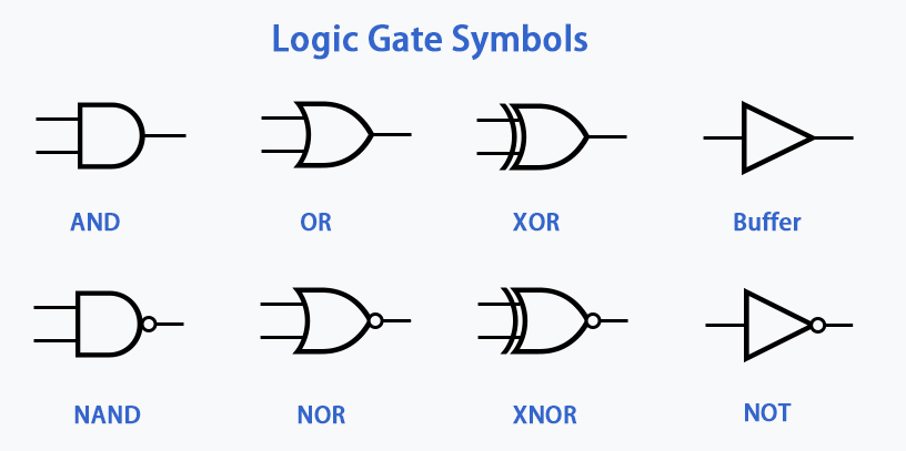
Types of Logic Gates
Several types of logic gates are available. However, we will focus on the main ones for now. Here is what to expect.

Classification of Logic Gates
Porte ET
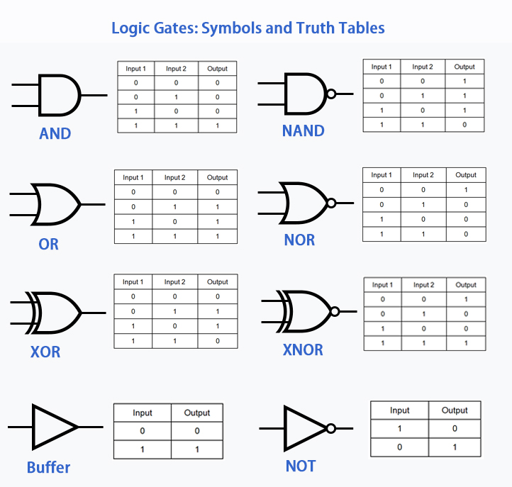
The AND gate produces a true output if both the inputs into the logic gate are true. It produces a false output even if one of the inputs is false or both. In this case, to get 1 as the output, both the inputs have to be 1.
Here is the truth table showing its operation
| Input 1 | Input 2 | Sortir |
|---|---|---|
| 0 | 0 | 0 |
| 0 | 1 | 0 |
| 1 | 0 | 0 |
| 1 | 1 | 1 |
Porte OU
This is another widely used logic gate in digital electronics. For this one, the output is true if one of the inputs is true. In case both inputs are false, then the output is also false. As a result, if you want an output to be 1, then at least one of the inputs should be 1.
Here is the truth table showing its operation.
| Input 1 | Input 2 | Sortir |
|---|---|---|
| 0 | 0 | 0 |
| 0 | 1 | 1 |
| 1 | 0 | 1 |
| 1 | 1 | 1 |
XOR Gate
This is also called the exclusive OR logical gate. It works by giving a true output only if one of the inputs is true but not both. If both inputs are true or false, you get a false output. So, to get 1 as the output, only one of the inputs needs to be 1, but if both are 1 or 0, the result is 0.
Here is the truth table showing its operation.
| Input 1 | Input 2 | Sortir |
|---|---|---|
| 0 | 0 | 0 |
| 0 | 1 | 1 |
| 1 | 0 | 1 |
| 1 | 1 | 0 |
NOT Gate
This logic gate reverses the current state of the input. It also only accepts one input compared to the others and gives a single output. In this case, if the input is 1, then the output is 0, and vice versa.
Here is the truth table showing its operation.
| Saisir | Sortir |
|---|---|
| 1 | 0 |
| 0 | 1 |
Porte NAND
This is the negated AND gate. It works as an AND gate mentioned above, but the output of the AND gate is passed through a NOT gate. Expect it to produce 0 if both inputs are 1 else the output is 1. It is simply a logical operator with a negation in the end.
Here is the truth table showing its operation.
| Input 1 | Input 2 | Sortir |
|---|---|---|
| 0 | 0 | 1 |
| 0 | 1 | 1 |
| 1 | 0 | 1 |
| 1 | 1 | 0 |
Porte NOR
You can also call it the NOT OR gate. It is a combination of the OR gate followed by the NOT gate. It produces a 1 only if both inputs are 0, else the output is false or 0.
Here is the truth table showing its operation.
| Input 1 | Input 2 | Sortir |
|---|---|---|
| 0 | 0 | 1 |
| 0 | 1 | 0 |
| 1 | 0 | 0 |
| 1 | 1 | 0 |
XNOR Gate
For XNOR, you have an XOR gate whose output is followed by the inverter. So, you only get a true output if both inputs are the same and false when the inputs are different. As such, you get a true output whether you have 1 or 0 as the two inputs.
Here is the truth table showing its operation.
| Input 1 | Input 2 | Sortir |
|---|---|---|
| 0 | 0 | 1 |
| 0 | 1 | 0 |
| 1 | 0 | 0 |
| 1 | 1 | 1 |
Uses of Logic Gates
Logic gates and logic circuits will generally have multiple applications. The most common one is being used as the core of computer architecture. The reason is to implement logic, arithmetic, and control functions.
Memory devices also use logic gates in various capacities to work properly. This includes storing and retrieving information.
Microprocessors and microcontrollers also rely on logic gates to process instructions and control system operations.
A logic gate simulator can also show how logic gates are key in digital signal processing, which involves tasks such as modulation, filtering, and demodulation. The same principle works for communication systems where the logic gates are key for encoding, processing, and decoding digital signals.
Consumer electronics such as smartphones, digital watches, and calculators use logic gates to function as expected. The same applies to automotive electronics, such as the safety system and engine control units.
Advantages and Limitations of Logic Gates
Advantages
- Expect fast switching speeds when working with logic gates. This is vital for rapid data processing applications.
- They usually consume less power, whether it is aNOT gate logic circuit or any other. This is vital for battery-powered electronics.
- The boolean logic operations done by logic gates are fundamental in digital calculations and decision-making.
- The logic gates are generally compact. This allows them to be integrated into the making of ICs. Even if they are compact, they still deliver good reliability.
- Mass production of the logic gates made their cost to be within the affordable range. This has also contributed to the spread of digital technology.
Limitations
- UN logic gate circuitis often susceptible to noise sensitivity, which sometimes leads to errors in operations.
- It is easy to see how basic logic gates operate, but things can get complicated quickly when you combine multiple gates.
- You may experience limited functionality with basic logic gates. This is why you sometimes need to add more logic gates to achieve a specific application.
Conclusion
As we have seen, logic gates are quite important in modern electronics. They are also fast at switching depending on the input, making them ideal for several applications. It is why you can get different devices being based on the operations of logic gates. Having low power consumption even drives the demand for such circuits. However, there might be a few limitations to keep in mind. This should help you design better logic gate circuits now that you have all important information about them.
Veuillez envoyer une demande de devis, nous vous répondrons immédiatement.
Questions fréquemment posées
What is a truth table in relation to logic gates?
This is a table showing the possible input combinations with their corresponding outputs. It basically helps you visualize how a logic gate works under different conditions.
Is it possible to build logic gates with basic electronic components?
Yes. Logic gates are built mainly by using components such as resistors and diodes. However, you can get modern circuits using ICs containing many gates for complex applications.
Can you combine multiple logic gates to form a single circuit?
Yes. Combining several logic gates can create complex circuits. Such combinations will be used to perform complex functions depending on the application.