What is an Operational Amplifier Integrator? Circuit, Design, Types, and Applications
Author:admin Date: 2025-06-20 08:23 Views:279
Op-Amp Integrator (with Derivation and Solved Examples)
Introduction
Un integrator amplifier is an electronic circuit designed to produce an output voltage proportional to the input voltage integral over time. Its work is to simulate the mathematical operation of integration using an operational amplifier or op-amp combined with a capacitor.
Un integrator amplifier will take the input voltage signal and then give you an output representing the cumulative effect of the input signal over time. You would have to perform the integration of the input voltage signal if you were to do it mathematically.
This type of circuit has many applications based on how it works. It can be used for wave shaping, analog-to-digital conversion, function generators, ramp generation, and many others.
Components of an Integrator Amplifier
Integrator amplifiers have three main components including an operational amplifier, a feedback capacitor, and an input resistor.
The operational amplifier is the active component in the circuit. It is responsible for providing signal integration and amplification. To achieve this functionality, it has an inverting configuration.
The feedback capacitor is connected between the inverting input and the output of the op-amp. Its discharging and charging characteristics are important for the integration process. Since the reactance of the capacitor depends on frequency, it will allow different frequencies to pass with varying levels of resistance. This enables integration to happen to the input signal over time.
The input resistor is connected between the inverting input and the op-amp’s input signal. Together with the feedback capacitor, it helps determine the integration time constant and the circuit gain.
Characteristics of an Integrator Amplifier
Whether you choose a Marantz integrator amplifier or any other brand, they tend to have similar characteristics. Because of how they are built and operate, some notable electrical characteristics include frequency response gain, transient response, and output impedance. Let us look at them below.
Frequency Response
For the ideal or best integrator amplifier, the gain decreases with frequency increase at the rate of 20dB per decade. However, having a resistor in parallel with the capacitor for a practical integrator makes it work as a low-pass filter with a -3 dB cutoff frequency.
When you go below the cutoff frequency, the circuit is no longer an ideal integrator, and the response deviates from the normal -20 dB per decade slope.
A real op-amp will have a limited gain-bandwidth product or GBWP, which will introduce an additional high-frequency pole in the frequency response. This will affect the integration range.
The gain of the 300-watt integrator amplifier is inversely proportional to the frequency. At a specific frequency or unity gain frequency, the gain is 1. The gain at different frequencies is usually determined based on the values of the resistor and feedback capacitor.
Input and Output Impedance
Un operational amplifier integrator’s impedance depends on the input resistor. Expect this to be very high.
The output impedance is very low, which means the circuit can now drive the other loads.
Transient Response
When you have a step voltage applied to the integrator amplifier input, the output voltage will ramp up or down linearly until it gets to the saturation voltage.
If you use a square wave signal at the input, expect to get a sawtooth waveform because of the feedback capacitor’s charging and discharging behavior.
The RC time constant of the input resistor and feedback capacitor helps determine the slope of the ramp in response to the step or square wave input.
The Working Principle of an Integrator Amplifier
As we had already mentioned, an integrator amplifier works by producing an output voltage proportional to the input voltage integral over time. Here is a breakdown of the different parts of the operation.
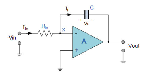
First, the integrator circuit has to be in the standard inverting amplifier configuration. This is where the input signal is connected to the inverting input of an op-amp.
We also have a capacitor connected to the feedback path. When the capacitor discharges or charges, it leads to the integration process.
When the input voltage is applied to the integrator amplifier, it flows through the input resistor and then into the feedback capacitor.
Expect the voltage across the capacitor to vary depending on the accumulated charge, which depends on the input current and the total time it takes to flow.
The output voltage directly depends on the voltage across the capacitor, which changes based on the integral of the input current over time.
So, how does the mathematical integration look like?
The relationship between the integrator amplifier’s input and output can be expected mathematically to better understand it. This is what it looks like:
Vout = -(1/RC) * ∫Vin dt
This equation shows how the output is the integral of the input voltage multiplied by the gain factor.
Applications of Integrator Amplifiers
Le best integrator amplifiers will have many functions. Some of the common applications for the integrator amplifier include:
- They are key in performing calculus operations in analog computers. This allows for solving differential equations.
- Since the integrator amplifiers can integrate the voltage input, this leads to a ramp-like output waveform, which is key in sweep circuits and similar applications.
- The integrators can also transform various input waveforms, such as converting square waves to triangle waves or sine waves to cosine waves.
- Such an op-amp is used in the design of certain analog-to-digital converters, particularly those used for performing integration over a defined period.
- The circuit can be good for charge amplifiers as well. These are important for applications such as piezoelectric transducers.
How to Design and Implement Integrator Amplifiers
UN good integrator amplifier will only work if you did the design right. Below are the steps to take for designing an integrator amplifier.
1. Choosing an op-amp
It is vital to select an op-amp suitable for the operation. Consider factors such as the offset voltage, input bias current, slew rate, and bandwidth. For example, the 741 op-amp can be used for low-frequency applications. However, higher-frequency or precision applications need a CMOS op-amp with a low offset voltage.
2. Choose the feedback capacitor
A feedback capacitor is crucial for the integration time constant. This is what influences how the circuit responds to different input frequencies. Having a larger capacitor means slower integration or longer time constant and vice versa.
3. Choose the input resistor
Selecting the input resistor is just as important. This is because the resistor, together with the capacitor, determines the integration time constant. So, choose a value for the resistor that, when combined with the value of the capacitor, gives you the desired integration time constant and avoids op-amp saturation.
4. Consider the input offset voltage
Op-amps come with an input offset voltage value that causes the output to drift towards the integrator circuit saturation. To mitigate this issue, you can add a large resistor parallel to the circuit’s feedback capacitor. This helps limit the DC gain.
5. Building the circuit
Now that you have the right parts to build a stereo integrator amplifier, this is how to proceed.
- Connect the input signal to the input resistor, which is connected to the op-amp’s inverting input.
- The feedback capacitor is connected between the same inverting input and the op-amp output.
- Ensure the resistor and capacitor are in a parallel connection to limit DC gain and prevent integrator saturation.
- The non-inverting input of the integrator is connected to ground.
Go ahead and test the circuit using different input signals and observe the output waveforms on an oscilloscope. If the output does not match the expected output, you may have to troubleshoot the issue.
How to Improve the Performance of Integrator Amplifiers
You are likely to face performance issues with an integrating amplifier. If you can deal with some issues, then the performance will improve. This can include minimizing DC offset, optimizing the capacitor and resistor values, and addressing low-frequency instability.
Addressing DC Offset and Saturation
It is important to have the feedback capacitor in parallel with the resistor. This limits DC gain, thus preventing the output from drifting to saturation, especially at low frequencies or due to the input offset voltage.
The input offset voltage also causes the output to drift towards saturation. So, it is best to minimize this offset by choosing the components carefully, including using a low-offset op-amp.
A shorting switch can be used as a temporary solution across the capacitor. Its job is to re-initialize the circuit, but it is not recommended as a long-term solution.
Optimize Frequency Response and Stability
One solution for this part is to choose the right capacitor. We recommend choosing a low-leakage capacitor, such as polypropylene film, to help minimize errors due to capacitor characteristics. Electrolytic capacitors are not the best for such applications.
Consider the RC time constant, as it also determines the frequency range of operation and integration time. Adjust the values to help extend the integrator amplifier’s dynamic range and accuracy.
The input impedance also affects an amplifier integrator circuit, so the right values of the input resistance are needed. Sometimes, a voltage follower can be used as the buffer stage if it is critical to achieve impedance matching.
Integrator vs. Differentiator Amplifiers

These two vary based on how they operate. An integrator amplifier performs the integration mathematical operation, taking the input signal and calculating its integral with respect to time. In this case, the output voltage is proportional to the area under the input voltage curve over time.
The differentiator amplifier also performs mathematical operations, but in this case, it is differentiation. It calculates the derivative of the input signal with respect to time. The output voltage in a differentiator amplifier is proportional to the change in the input voltage.
| Fonctionnalité | Integrator | Differentiator |
|---|---|---|
| Operation | Integration | Differentiation |
| Sortir | Proportional to the input integral | Promotional to the input derivative |
| Component | Feedback capacitor, input resistor | Input capacitor, feedback resistor |
| Noise | Reduces noise | Amplifies noise |
| Stability | More stable operation | Less stable at high frequencies |
Conclusion
An integrator amplifier is critical in various applications and that is why you have to get it right at the design stage. You can still consider getting one from top brands. Examples include the Onkyo integrator amplifier, the Denon integrator amplifier, the Rotel integrator amplifier, and others. Always keep in mind how the integrator amplifier works so that it can be fine-tuned to achieve the desired results. With the right setup, you can expect the right results once you use it.
Veuillez envoyer une demande de devis, nous vous répondrons immédiatement.
Questions fréquemment posées
What is the difference between an ideal and a practical integrator amplifier?
In the case of an ideal integrator amplifier, you assume perfect conditions. This means no losses, zero offset, and infinite gain. As for a practical integrator, you factor in real-world factors such as offset voltage, input bias current, and additional components key in stabilizing the output of the op-amp and preventing saturation.
What makes the integrator amplifier saturate?
Saturation can occur because of a continuous DC input, input bias current, or offset voltages, which gradually charge the capacitor and push the op-amp to its supply limits.
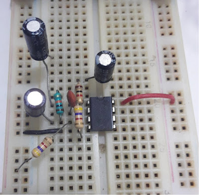
Is it possible to simulate an integrator amplifier circuit?
You can build one using a breadboard and other components of an integrator amplifier. Simulating it using software such as Multisim, LTspice, and Proteus is the other solution. Simulations are great to ensure you can fine-tune the amplifier to work as you want before implementing it.