What Is a Passive Low Pass Filter? How It Works and When to Use It
Author:admin Date: 2025-05-20 07:38 Views:1135
Introduction
A passive low pass filter is an electrical circuit that allows low-frequency signals to pass through while reducing or attenuating the high-frequency signals. It is a passive filter because it uses passive components such as capacitors, resistors, and inductors to achieve this operation.
We go deeper into understanding what a passive low pass filter is all about, including the types, how to design, operations, and much more. We can assure you of having a better understanding of such filters in the end.
Types of Passive Low Pass Filters
There are several ways of categorizing passive low-pass filters, but the main options on the market are first—and second-order low-pass filters.
First Order Low Pass Filters
The 1st order passive low pass filters, they are the simplest as they consist of single RC or RL components as part of implementing the filter. The name first order is because their frequency response comes with a slope or roll-off rate of -20 dB per decade.
RC Low Pass Filter

In this case, a passive RC low-pass filter consists of a resistor (R) and a capacitor (C) connected in series.
The capacitor will act as the voltage divider, with the output measured across it. The low-frequency signals will pass through the circuit with minimal attenuation. The capacitor’s impedance, in this case, is high, which is why the higher frequencies will be attenuated more.
The transfer function gives the frequency response of a first-order RC low pass filter. Here is the equation.

RL Low Pass Filter

This is probably less common than the RC low-pass filter, but it is worth considering as well. In this case, the components include the inductor (L) and resistor (R), which are connected in series to form the filter. The output, in this case, is taken across the resistor in the circuit.
To get the frequency response, you use this transfer function

Second Order Passive Low Pass Filters
The 2nd order passive low pass filter will have a higher roll-off than the first-order options. This can be achieved by cascading two first-order low pass filters.
Since you are combining two first-order filters, you end up with a roll-off rate of -40dB per decade since each first-order low-pass filter will have -20 dB per decade.
A roll-off rate means that frequency increases by 10 times, and attenuation increases by 100 times. A higher roll-off rate results in more frequency suppression than the cut-off frequency of a low-pass filter.
RC-RC Low Pass Filter
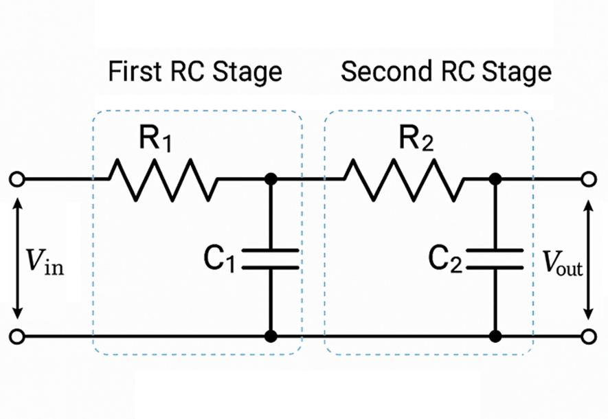
For this kind of setup, you have RC passive low pass filter for the first stage and the same for the second stage.
At low frequencies, the capacitor acts as if it is open; thus, no current flows through it. As such, the voltage drop is measured across R1 and R2.
The transfer function for the high pass filter in this setup will be:

RLC Low Pass Filter

This is another setup worth looking at. Use the equation ω = 1/√LC to find the cut-off frequency. After this frequency, the capacitor is short to ground while the inductor becomes open. This makes the output voltage to be zero in the stopband.
In the pass band or low frequency, the inductor acts as short while the capacitor is open. This allows the signal to flow from the voltage source to the output voltage. For this case, the transfer function will be:

Applications of Passive Low Pass Filters
The RC passive low pass filter or any other will have multiple applications to expect. Here are a couple of examples to expect.
Audio crossovers in speakers
The low-pass filters are vital for directing the low-frequency sounds to the subwoofer, while the higher-frequency sounds go to the other speaker types. This ensures that the speaker system operates optimally.
Noise filtering in power supplies
Yes, power supplies could also use such a filter type. This is important to eliminate high-frequency ripple and noise from AC power, resulting in clean and steady DC voltage for your devices.
Anti-aliasing filters
These filters are important for the analog-to-digital conversion process. The low-pass filter removes the high-frequency components, which would lead to distortion of the digitized signal.
RF Applications
Passive low-pass filters can also be used in radio frequency applications, where they filter out unwanted interference from other signals. The result is having a clear reception and transmission.
Sensors and control systems
Many control and sensor systems need low-pass filters to remove high-frequency noise and interference, which may corrupt the control system’s operation or the measured signal.
Advantages and Limitations
Advantages
- Passive filters are generally easy to build and design as well. You only need basic passive components such as inductors, capacitors, and resistors.
- These passive low pass filters are generally inexpensive. This is because the components are affordable.
- No need for external power to make such a circuit work
- No complex configurations are needed to implement a passive low pass filter design
Limitations
- When you analyze the passive low pass filter circuit diagram, you will notice they often have limited gain.
- It’s not the best choice when you need to achieve precise and steep roll-offs.
- They can be affected by load impedance, which influences the load you can connect to them.
Passive vs. Active Low Pass Filter
When you look at the active and passive low-pass filter schematic, you can clearly see the difference between the two. In the active filters, you can expect them to offer more features than the passive counterparts. Here, you get more features such as gain, load driving, and more adaptable characteristics.
The passive filters are generally cheaper, more reliable, and simpler to design and build.
Looking at the performance differences, we see that active filters can gain more. This is not the same as with passive filters, as the gain is not more than one.
The active filters also offer load-driving capability. This is especially true for those using the op-amps. They can drive higher impedance loads.
How about frequency response? The frequency response of active filters is less susceptible to changes in component values and temperature. This is not the same for the passive filters.
The active filters also offer better stability for a complex multi-stage application. Just make sure you use proper decoupling techniques.
Troubleshooting Passive Low Pass Filters
- Always double-check your circuit layout. A slight difference in how it is wired can affect the expected results.
- Check the values of the components. Having the wrong values affects the cutoff frequency.
- Inspect the breadboard for poor or band connections. It is the same for a PCB. check for cracked solder joints or broken pads.
- Check your source signal and the load as well. The input signal needs to be within the rated voltage range. As for the load, improper loading can distort the frequency response.
- Passive components can fail. Check if you have a discolored resistor that shows it is a burned or damaged inductor, which may lead to high resistance or reads open.
Conclusion
The passive low-pass filter has several applications you can consider using. Just ensure you are using the right components for the application. It might be good to take more time at the design stage to choose the correct values for components to achieve your goals. Keep improving your design depending on how you use it to get the right results. Also, keep in mind the application environment. Sometimes, the temperature can affect the performance of the passive low pass filter.
Please send RFQ , we will respond immediately.
Frequently Asked Questions
Is impedance significant when designing a passive filter?
Yes. It affects how the signals interact with the passive low-pass filter. A mismatch between the load impedance, filter, and source can alter the overall cutoff frequency and distort the signal.
How can you simulate a passive low pass filter?
There are multiple tools you can consider. Multisim Live and LTspice are some of the top choices if you want to simulate the performance of your filter design before building it.
What is the typical roll-off for a passive low pass filter?
The first-order passive low pass has a roll-off rate of -20dB per decade. This means that the signal attenuates by 20 decibels for every tenfold increase in frequency beyond the filter’s cut-off point.


