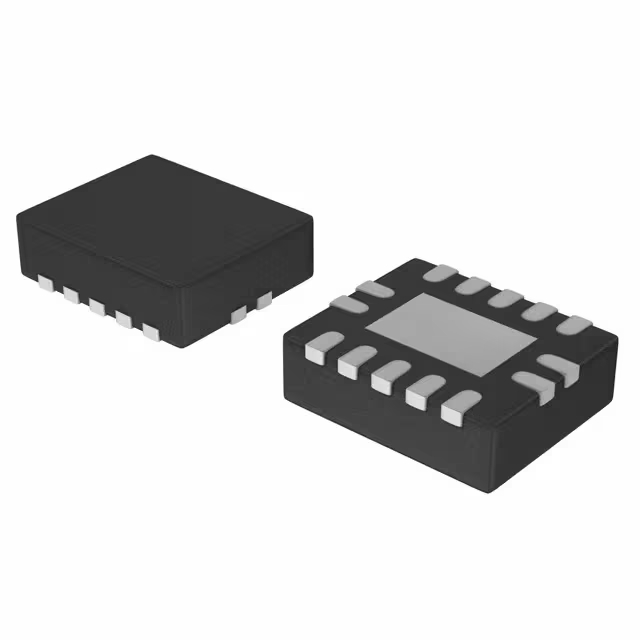
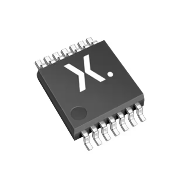
When using AD2S1210ASTZ, keep in mind the MODE pin decides pin functions: SPI mode (high) or parallel mode (low). EXC outputs directly drive resolvers but benefit from inductors for stability. Use differential inputs (SIN/COS) with low noise routing. Pull RESET low at startup for proper initialization. REFOUT offers a voltage reference for ADCs—don’t overload it. Provide a stable 5V supply; VDRIVE can be 3.3V or 5V based on your MCU logic.
AD2S1210ASTZ datasheet & price | CMS Conv. Resolver
The AD2S1210ASTZ is a high-performance resolver-to-digital converter (RDC) with a 10- to 16-bit resolution, designed for motion control and automation applications. Check its datasheet (PDF) for detailed specifications and price information for market pricing.
- Taper: R/D Converter
- Nombre de canaux : 2
- Résolution (bits) : 10, 12, 14, 16 b
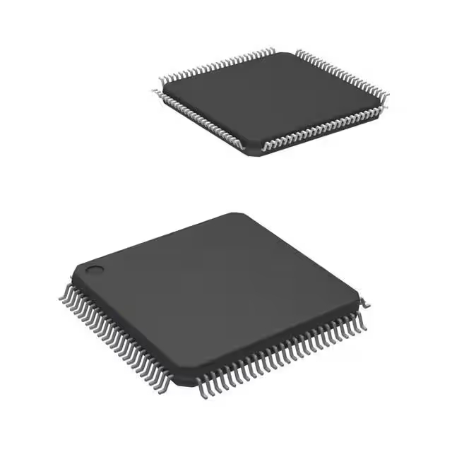
- Emballer: 48-LQFP

Livraison GRATUITE pour les commandes supérieures à HK$250.00

Réponse rapide, devis rapide

Expédition rapide, pas de soucis après-vente

Chaîne originale, garantie de produits authentiques
AD2S1210ASTZ
If you’re designing precise motion control systems, like servo drives, robotics, or aerospace applications, the AD2S1210ASTZ RDC chip is perfect for you.
Its 16-bit resolution divides each rotation into 65,536 precise steps, giving extremely smooth and accurate positioning. It has an integrated excitation generator (adjustable from 2kHz to 20kHz), simplifying your circuit and wiring.
It supports both parallel and serial outputs, so connecting it to your microcontroller or PLC is easy. The chip also includes a dedicated speed register, ideal for closed-loop motor control. Plus, built-in fault detection ensures you quickly spot any signal issues.
Its LQFP-48 package is compact, SMT-friendly, and works reliably from -40°C to +125°C, ideal for industrial environments.
AD2S1210ASTZ Pinout Diagram

| Numéro de code PIN | Nom de la broche | Taper | Description |
|---|---|---|---|
| 1 | RES1 | Saisir | Reset pin (active low) |
| 2 | CS | Saisir | Chip enable / Chip select |
| 3 | RD | Saisir | Parallel read control (active low) |
| 4 | WR̅ / FSYNC | Saisir | Write control / SPI sync signal |
| 5 | DGND | Pouvoir | Digital ground |
| 6 | DVDD | Pouvoir | Digital power supply (+5V) |
| 7 | CLKIN | Saisir | External clock input (optional) |
| 8 | XTALOUT | Sortir | Crystal output (if using internal oscillator) |
| 9 | SOE | Saisir | Output enable in parallel mode |
| 10 | SAMPLE | Saisir | Start new sample (angle & speed) |
| 11 | DB15 / SDO | Sortir | Parallel data bit 15 / SPI output |
| 12 | DB14 / SDI | Saisir | Parallel data bit 14 / SPI input |
| 13 | DB13 / SCLK | Saisir | Parallel data bit 13 / SPI clock |
| 14–27 | DB12–DB0 | E/S | Parallel data bits 12 to 0 |
| 28 | UN | Sortir | Encoder A signal output |
| 29 | B | Sortir | Encoder B signal output |
| 30 | NM | Sortir | Encoder N (index) signal output |
| 31 | DIR | Sortir | Direction output (high = forward) |
| 32 | RÉINITIALISER | Saisir | Main reset pin (active low) |
| 33 | LOT | Sortir | Loss of tracking indicator (low = loss) |
| 34 | DOS | Sortir | Data overflow signal (high = error) |
| 35 | A1 | Saisir | Address bit A1 (parallel register access) |
| 36 | A0 | Saisir | Address bit A0 (parallel register access) |
| 37–38 | EXC | Sortir | Excitation signal output (differential) |
| 39 | AGND | Pouvoir | Analog ground |
| 40 | SIN | Saisir | Resolver SIN input |
| 41 | SINLO | Saisir | SIN differential negative input |
| 42 | COS | Saisir | Resolver COS input |
| 43 | COSLO | Saisir | COS differential negative input |
| 44 | AVDD | Pouvoir | Analog power supply (+5V) |
| 45 | REFOUT | Sortir | Reference voltage output (for ADC) |
| 46 | REFBYP | E/S | Reference bypass capacitor connection |
| 47 | RES0 | Saisir | Reset config (used with RES1) |
| 48 | RES1 | Saisir | Same as above |
AD2S1210ASTZ Equivalent Resolver Converter

| Paramètre | AD2S1210ASTZ | AD2S1210-EP | AD2S1210ESZ |
|---|---|---|---|
| Fabricant | ADI | ADI | ADI |
| Resolution | 10–16 bits | 10–16 bits | 10–16 bits |
| Excitation Frequency | 2 kHz–20 kHz (adjustable) | 2 kHz–20 kHz (adjustable) | 2 kHz–20 kHz (adjustable) |
| Interface | SPI serial / parallel | SPI serial / parallel | SPI serial / parallel |
| Temperature Range | −40°C ~ +125°C | −55°C ~ +125°C | −40°C ~ +125°C |
| Qualification Grade | AEC-Q100, ASIL B automotive | AQEC, aerospace/military certified, ASIL B grade | Standard industrial grade |
| Type de colis | 48-pin LQFP | 48-pin LQFP | 48-pin LQFP |
| Supply Status | Standard industrial, automotive supply | Certified for aerospace/military, longer lead time | Standard industrial, stable supply |
| Pricing Position | Mid-range | Higher (certified) | Lower (industrial grade) |
If you’re considering replacements for the AD2S1210, keep this in mind: AD2S1210-EP is for harsh environments like military and aerospace, with wider temperature range (–55°C), higher cost, and longer lead times. AD2S1210ESZ has identical functionality but lacks automotive-grade certification, fine for industrial use but not recommended for automotive. All these models share identical footprints and pinouts, allowing easy swaps. Just double-check your project’s certification needs before picking.
AD2S1210ASTZ Resolver Interface Circuit

When connecting a Resolver to the AD2S1210, remember this analog front-end circuit. Series resistors (1kΩ) and clamping diodes protect inputs. Simple RC filters remove noise for stable readings. Optional 2.5V bias centers signals if needed. For long-distance wiring, a differential termination resistor RA improves signal integrity.
AD2S1210ASTZ Motor Encoder Application
When using the AD2S1210 in servo systems, it converts resolver signals into precise digital angle and speed data, replacing traditional encoders. It’s highly resistant to interference, perfect for harsh conditions (high temperature, vibration, EMI). With up to 16-bit accuracy and built-in speed calculation, it greatly simplifies control tasks. Ideal applications include robotics joints, CNC machines, EV motor drives, and aerospace equipment.
AD2S1210ASTZ Position Feedback Wiring
When using AD2S1210ASTZ for motor position feedback, resolver outputs (SIN/COS) connect directly to the chip’s differential inputs. The EXC pin provides excitation (usually 6.25–10kHz). Use simple RC filters for input protection. The chip converts signals to digital angle data sent via SPI or parallel to your MCU/DSP for precise control. Connect RESET for initialization, LOS/DOS pins detect signal faults.
Plus comme ça
Ajouter également au panier
Produits connexes
Veuillez envoyer une demande de devis, nous vous répondrons immédiatement.
Copyright © 2024 Tous droits réservés


