
CP2102 USB to UART Bridge Controller Driver
- Protocol Supported: -
- Operating Supply Current: -
- On Resistance - Max: -
- Package: QFN-28


FREE delivery for orders over HK$250.00

Quick response, quick quotaton

Flash shipment,no worries after sales

Original channel,guarantee of the authentic products
CP2102 Serial Port Module Install Driver on Windows
Cp2102
The CP2102 is a highly integrated USB-to-UART bridge that simplifies your circuit design by combining several key features in one package. It includes a USB controller, UART interface, oscillator, reset circuitry, and voltage regulator, reducing the need for external components.
It supports USB 2.0 Full-Speed (12 Mbps) and provides a 3.3V output to power low-voltage devices. The CP2102 is flexible, offering data formats with 5, 6, 7, or 8 data bits, 1, 1.5, or 2 stop bits, and options for odd, even, or no parity. The baud rate can range from 300 bps to 1 Mbps.
It also has built-in buffers, including 576 bytes for receiving and 640 bytes for transmitting, and supports both hardware and software flow control. With its virtual COM port (VCP) driver, the CP2102 works seamlessly on Windows, Linux, and macOS, making it a great solution for replacing RS-232 interfaces with USB.
Cp2102 Pinout

| Pin No. | Pin Name | Description |
|---|---|---|
| 1 | VBUS | USB Power Input (5V) |
| 2 | D+ | USB Data Positive Line |
| 3 | D- | USB Data Negative Line |
| 4 | GND | Ground |
| 5 | VDD | Power Supply (3.3V) |
| 6 | TXD | UART Data Transmit (Transmit) |
| 7 | RXD | UART Data Receive (Receive) |
| 8 | RTS | Request to Send (Output, Low-Level Active) |
| 9 | CTS | Clear to Send (Input, Low-Level Active) |
| 10 | DTR | Data Terminal Ready (Output, Low-Level Active) |
| 11 | DSR | Data Set Ready (Input, Low-Level Active) |
| 12 | DCD | Data Carrier Detect (Input, Low-Level Active) |
| 13 | RI | Ring Indicator (Input, Low-Level Active) |
| 14 | RESET | Reset Pin (Low-Level Active) |
| 15 | SUSPEND | USB Suspend (Low-Level Active) |
| 16 | VREGIN | External Power Input (For Internal Regulators) |
| 17 | VDDIO | I/O Power Supply Input (3.3V or 5V) |
| 18-28 | NC | Not Connected |
The CP2102 has several key pins for power, data, and control. VBUS (Pin 1) provides 5V from the USB host, while VDD (Pin 5) supplies a 3.3V output for powering external devices. VREGIN (Pin 16) is used to connect an external power source, such as 5V, to the internal regulator, and VDDIO (Pin 17) sets the I/O voltage level, supporting either 3.3V or 5V. For USB communication, D+ and D- are the data lines, connecting to the USB host’s corresponding pins. The TXD, RXD, RTS, CTS, DTR, DSR, DCD, and RI pins handle the full UART signals, including data transfer and hardware flow control, which is essential for reliable communication. Lastly, RESET (Pin 14) is used to reset the device, and SUSPEND (Pin 15) indicates when the USB is in suspend mode. These pins are essential for setting up power, data, and control in your projects.
Cp2102 Usb Uart Chip Alternative

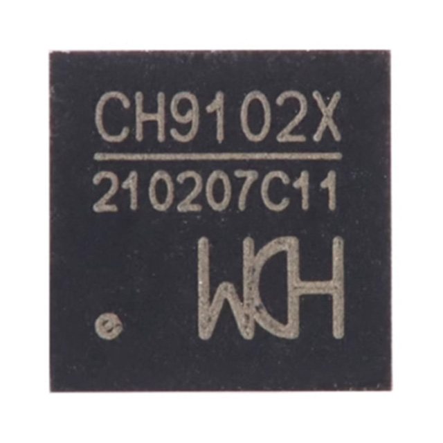
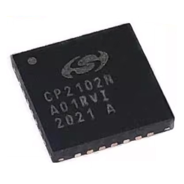
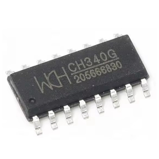

| Parameter | CP2102 | CH9102X | CP2102N | CH340G | FT232RL |
|---|---|---|---|---|---|
| Package | QFN-28 | QFN-28 | QFN-28 | SOP-16 | SSOP-28 |
| Max Baud Rate | 1 Mbps | 4 Mbps | 3 Mbps | 1 Mbps | 3 Mbps |
| GPIO Pins | 0 | 6 | 0 | 0 | 4 |
| Voltage Range | 3.0V – 3.6V | 3.3V / 5V | 3.0V – 3.6V | 5V | 3.3V / 5V |
| Crystal Requirement | Internal, No External Crystal Required | Internal, No External Crystal Required | Internal, No External Crystal Required | Internal, No External Crystal Required | Internal, No External Crystal Required |
| Driver Support | Good | Good | Good | General | Excellent, Industrial Grade |
| Cost | Moderate | Moderate | Moderate | Low | High |
| Application | General, Development Board Debugging | General, High-Speed Transmission | General, Low-Power Designs | Low-cost Applications, DIY Projects | Industrial Applications, High Stability |
When you’re looking for a replacement chip in your design, there are a few things you’ll want to keep in mind. If you’re directly swapping out an existing chip, choosing something like the CH9102X or CP2102N makes sense since they both have the same QFN-28 package, which fits easily into your PCB layout.
If speed is a priority and you need faster data transmission, go for the CH9102X—it can handle up to 4 Mbps. Also, if your project requires extra GPIO pins for additional control signals, CH9102X offers six GPIO pins, giving you greater flexibility.
For industrial or mission-critical applications where reliability matters most, consider using the FT232RL. It has wide driver support, excellent stability, and is trusted in demanding environments.
Finally, if you’re working with a tight budget or doing DIY projects, the CH340G is a great, affordable option that’s reliable enough for everyday use and widely popular among hobbyists.
Cp2102 Serial Converter Circuit

Let me walk you through this USB-to-serial circuit using the CP2102 chip, which helps your computer communicate easily with microcontrollers or other serial devices. First off, the USB connector (J1) gives you a 5V power supply through VBUS, and D+ and D- handle your data lines directly to the CP2102. There’s also some essential ESD protection (D1, D2, D3) to keep things safe from static electricity.
Now, you’ll notice a few capacitors like C1 and C2—they smooth out your chip’s power supply, making sure everything runs stable. Extra capacitors (C3, C4, C5) further reduce any noise from your USB power source.
The CP2102 itself manages USB communication and provides key serial signals like RXD and TXD for data exchange. It also supports optional handshake signals (RTS, CTS, etc.) for advanced setups, plus sleep-mode signals to manage power use.
Lastly, those indicator LEDs (D4, D5, D6) conveniently show you the connection and communication status at a glance.
Cp2102 Arduino Communication Example

Let’s break down this USB-to-serial communication circuit using the CP2102 chip and ATmega328P microcontroller. This setup is perfect for connecting your ATmega328P to a computer through USB. The CP2102 takes care of converting USB signals into standard serial signals, like RX and TX, making it possible for your microcontroller to communicate with the computer.
The CP2102 connects to the USB port and uses standard signals like VBUS, D+, D-, and GND for data transfer. It’s also powered by a 100nF capacitor to keep the voltage stable. On the other side, the ATmega328P gets a reset signal from the CP2102’s DTR pin, which is useful for things like bootloading.
For programming, the ICSP interface allows you to connect an external programmer. The TXD and RXD pins handle the data transfer between the CP2102 and the ATmega328P.
Overall, this is a typical USB-to-serial bridge used in Arduino-style boards, providing easy USB communication and programming for the ATmega328P.
Cp2102 Ttl to Rs232 Wiring
Basic Wiring:
| CP2102 Pin | RS232 Pin | Description |
|---|---|---|
| TXD | RX | CP2102 Transmit → RS232 Receive |
| RXD | TX | CP2102 Receive ← RS232 Transmit |
| GND | GND | Common ground |
| RTS | CTS (optional) | Optional for hardware flow control |
| DTR | DCD (optional) | Optional for hardware flow control |
Here’s an important thing to keep in mind when using the CP2102 with RS232 devices: the CP2102 works with TTL voltage levels, typically 3.3V or 5V, while RS232 uses much higher voltage levels, like +12V and -12V, for its signals. That means you can’t directly connect the CP2102 to an RS232 device.
What you’ll need is a level shifter circuit or an RS232-to-TTL converter, like the MAX232 IC, to handle the voltage conversion. The MAX232 is perfect for this because it takes the +12V and -12V RS232 signals and converts them down to the 3.3V or 5V TTL levels that the CP2102 uses.
So, remember, a level shifter IC is essential when working with RS232 to make sure your devices can communicate without damaging each other!
Cp2102 Driver for Linux Mac
Here’s a simple guide to set up the CP2102 on both Linux and macOS:
On Linux: Most modern Linux distros, like Ubuntu, Debian, and Fedora, already include the CP210x driver, so you don’t need to install anything extra. To check if your device is recognized, just plug in the CP2102 and run this command:
dmesg | grep tty
You should see something like /dev/ttyUSB0. If you can’t access the device, add your user to the dialout group by running:
sudo usermod -aG dialout $USER
Then log out and back in. Also, make sure you’re using a data-capable USB cable, as some only charge and don’t support data transfer.
On macOS: First, download the CP210x VCP driver from Silicon Labs. After installation, macOS might block the driver from an unverified developer, so go to System Preferences > Security & Privacy and click Allow. Restart your system to apply the changes. Once done, check for the device with:
ls /dev/cu.*
Make sure you’re using a driver compatible with your macOS version.
Cp2102 Board to Esp32 Connection
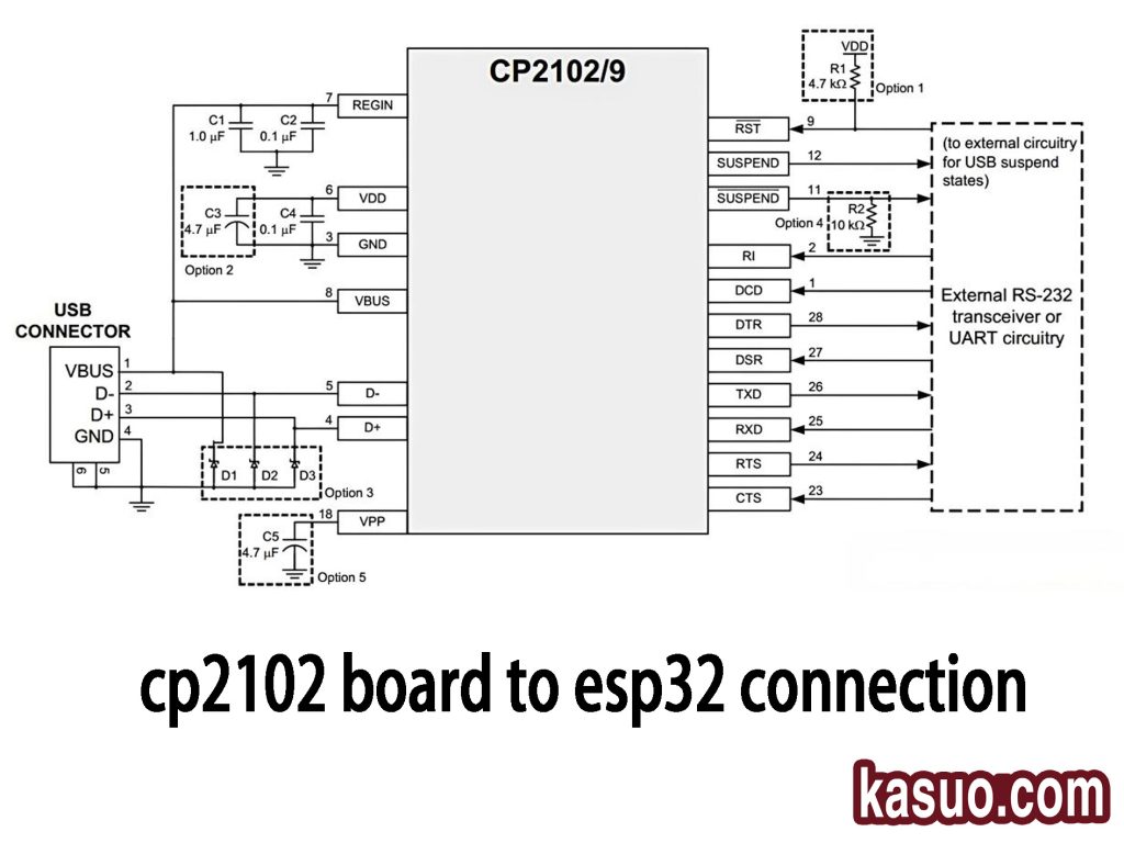
Here’s how to connect the CP2102 USB-to-serial module to the ESP32:
USB Connector Pins:
-
VBUS: This is the 5V power supply from the USB, which connects to the CP2102’s power pin.
-
D+ and D-: These are the data lines that carry communication between the computer and CP2102.
-
GND: Ground connection.
CP2102 Pins:
-
TXD (Transmit Data): Sends data from CP2102 to the ESP32’s RXD pin.
-
RXD (Receive Data): Receives data from the ESP32’s TXD pin.
-
RTS and CTS: Optional hardware flow control pins.
-
DTR: Controls the reset of the ESP32 through its EN pin for automatic firmware upload.
ESP32 Pins:
-
TXD: This is the receive pin on the ESP32, connected to CP2102’s RXD.
-
RXD: This is the transmit pin on the ESP32, connected to CP2102’s TXD.
-
EN: This pin is controlled by DTR to automatically reset the ESP32.
-
IO0: Used to trigger the ESP32’s download mode, controlled by CP2102’s RTS pin.
These simple connections let you program the ESP32 over USB using the CP2102!
Cp2102 Usb Connection Issues
If you’re having trouble with your CP2102 connection, here’s how you can troubleshoot. If the device isn’t recognized, it might be because the driver wasn’t installed properly. On Windows, make sure you’ve installed the right driver from Silicon Labs. On Linux, most distributions already have the CP210x driver built-in, but you can load it manually using sudo modprobe usbserial and sudo modprobe cp210x. For macOS, download and install the correct driver from Silicon Labs. If you can’t communicate with the device, check that the driver is up to date and ensure your serial settings, like baud rate and data bits, are correct. You can check if the device is listed with ls /dev/ttyUSB* on Linux/macOS. If the driver installation fails, especially on macOS, you may need to go into System Preferences > Security & Privacy and click “Allow” to unblock the driver. On Windows, update the driver in Device Manager. If the device keeps disconnecting or is unstable, try using a different USB cable and connect it directly to your computer rather than through a hub. Lastly, if the device won’t enter download mode, make sure the DTR and RTS pins are connected to the EN and IO0 pins on the ESP32. You might need to manually pull IO0 low and press the EN button to get it into download mode.
Cp2102 Tx Rx Wiring Guide
First, understand that the CP2102 has two important pins:
-
TXD (Transmit Data): This pin sends data from the CP2102 to your device.
-
RXD (Receive Data): This pin receives data from your device into the CP2102.
Now, for the wiring:
-
CP2102 TXD to target device RXD: This sends data from the CP2102 to your device.
-
CP2102 RXD to target device TXD: This receives data from your device into the CP2102.
A couple of things to keep in mind:
-
Voltage Compatibility: Make sure the voltage levels between your CP2102 and the target device match (typically 3.3V or 5V).
-
Flow Control: For simple setups, just connect TXD and RXD, but if you’re working on more complex applications, you might need to use flow control pins like RTS and CTS.
-
USB Cable: Always use a USB cable that supports data transfer; otherwise, the communication won’t work.
More Like This

MC5430F
Motorola

JD54LS51BCA
National Semiconductor

USPLSI2032VE-110LB49
Lattice Semiconductor Corporation
74S22PC
Rochester Electronics, LLC

9504DC
National Semiconductor

9005PC
National Semiconductor

9007DC
National Semiconductor
9004DC
National Semiconductor

SN74HC804DWR
Texas Instruments
SN700863DWR
Texas Instruments
4001BDMQB
National Semiconductor
54F02FMQB
National Semiconductor
Also Add to Cart

R1210N262D-TR-FE
Nisshinbo Micro Devices Inc.

CJ431
Jiangsu Changjing Electronics Technology Co., Ltd.
IDT74LVCHR16646APAG8
Renesas Electronics America Inc

S1ZB60-7062
Shindengen

ISL9307IRTAANLZ-T
Renesas Electronics America Inc
XRT75L03DIV
MaxLinear, Inc.

ISL12028IVZ
Intersil

MCP3423T-E/UN
Microchip Technology
SI3200-GS
Skyworks Solutions Inc.

8N3SV76KC-0034CDI
Renesas Electronics America Inc

89HP0504PBZBNRG
Renesas Electronics America Inc

MAX692AESA
Analog Devices Inc./Maxim Integrated
Related Products
MC5430F
Motorola
JD54LS51BCA
National Semiconductor
USPLSI2032VE-110LB49
Lattice Semiconductor Corporation
74S22PC
Rochester Electronics, LLC
9504DC
National Semiconductor
9005PC
National Semiconductor
9007DC
National Semiconductor
9004DC
National Semiconductor
SN74HC804DWR
Texas Instruments
SN700863DWR
Texas Instruments
4001BDMQB
National Semiconductor
54F02FMQB
National Semiconductor
DM54S20W/883
National Semiconductor

MC3129L
Motorola
4071BDM
National Semiconductor
MC9814P
Motorola
MC9825P
Motorola

74AC11000NS
Texas Instruments
MC5420L
Motorola
MC5401L
Motorola
MC5401F
Motorola
SN74H61N
Texas Instruments
MC5410F
Motorola
MC5430L
Motorola

SN74AS138N-J
Texas Instruments
CD4023BCN
Fairchild Semiconductor
4019BDC
National Semiconductor
74H40DC
National Semiconductor
5420FMQB
National Semiconductor
4025BDM
National Semiconductor
Please send RFQ , we will respond immediately.
