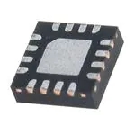
ES9018K2M DAC | Datasheet, Review, Chip, PDF
- Taper: Reference Stereo
- Type de sortie : -
- Polarity: -
- Emballer: -

Livraison GRATUITE pour les commandes supérieures à HK$250.00

Réponse rapide, devis rapide

Expédition rapide, pas de soucis après-vente

Chaîne originale, garantie de produits authentiques
ES9018K2M + BLUETOOTH I2S
es9018k2m
If you’re looking to build a high-quality audio project, the ES9018K2M DAC is an excellent choice. It can handle ultra-high-resolution audio, up to 32-bit/384kHz PCM, and supports native DSD formats including DSD64, DSD128, and DSD256, giving you exceptional clarity and detail.
You’ll notice its impressive dynamic range of 127 dB, making your music sound rich and lifelike. Plus, with ultra-low distortion (THD+N as low as -120 dB), you get clean, pure sound without any annoying background noise.
It’s super flexible, supporting various audio formats like I²S, left-justified, right-justified, and DSD. Its unique HyperStream™ technology cuts down jitter, giving you smoother audio. And it’s incredibly power-efficient—perfect if you’re designing portable audio gear like USB DACs or headphone amps.
Compact packaging helps save PCB space, ideal for portable devices, high-end desktop audio systems, professional recording equipment, car audio setups, and wireless audio solutions.
es9018k2m pinout schematic

| Numéro de code PIN | Nom de la broche | Description |
|---|---|---|
| 1 | XI | Main clock input (MCLK), audio synchronization |
| 2 | XO | Crystal oscillator output, connects to crystal or oscillator |
| 3 | RESETB | Reset pin, active low |
| 4 | SDA | I²C data line, chip configuration |
| 5 | SCL | I²C clock line, chip configuration |
| 6 | ADDR | I²C address selection pin, sets chip address |
| 7 | DATA_CLK | PCM/DSD/SPDIF data clock input |
| 8 | DATA1 | PCM/DSD/SPDIF data input 1 |
| 9 | DATA2 | PCM/DSD/SPDIF data input 2 |
| 10 | GPIO1 | General-purpose IO 1, configurable as SPDIF input/output |
| 11 | GPIO2 | General-purpose IO 2, configurable as SPDIF input/output |
| 12 | DVCC | Digital power input (1.8V or 3.3V) |
| 13 | GND | Sol |
| 14 | AVCC_L | Left channel analog power input (3.3V) |
| 15 | AVCC_R | Right channel analog power input (3.3V) |
| 16 | VCCA | Analog power input (3.3V) |
| 17 | DACL | Left channel analog voltage output |
| 18 | DACLB | Left channel inverse analog voltage output |
| 19 | DACR | Right channel analog voltage output |
| 20 | DACRB | Right channel inverse analog voltage output |
| 21 | DVDD | Digital core power input (1.8V) |
| 22 | NC | No connection pin, leave unconnected |
| 23 | NC | No connection pin, leave unconnected |
| 24 | NC | No connection pin, leave unconnected |
| 25 | NC | No connection pin, leave unconnected |
| 26 | NC | No connection pin, leave unconnected |
| 27 | NC | No connection pin, leave unconnected |
| 28 | NC | No connection pin, leave unconnected |
When you’re using the ES9018K2M DAC, there are a few practical tips you should keep in mind to ensure it runs smoothly. First, give it stable power—both the digital pins (DVCC, DVDD) and the analog pins (AVCC_L, AVCC_R, VCCA) typically run at either 1.8V or 3.3V, depending on your system.
Make sure the master clock (MCLK) frequency matches your chosen audio format. For PCM audio, it’s usually more than 24 times your sampling rate. Use the I²C pins (SDA and SCL) to configure the chip, and remember to set the correct address if you’re using multiple devices.
Your audio data inputs (DATA_CLK, DATA1, DATA2) must follow the timing specs in the datasheet carefully. For the analog outputs (DACL, DACLB, DACR, DACRB), you’ll need external circuitry—like op-amps—to convert current outputs to usable voltage signals.
Lastly, ensure proper heat dissipation and keep your analog and digital grounds separate on your PCB. Don’t forget to manage the RESETB pin correctly at startup. Following these steps ensures high-quality sound and stable operation.
es9018k2m equivalent dac

| Paramètre | ES9018K2M | ES9028Q2M | ES9038Q2M | ES9039Q2M | PCM1792A | AK4490EQ |
|---|---|---|---|---|---|---|
| Type de colis | 28-QFN | 32-QFN | 30-QFN | 32-QFN | 28-SSOP | 32-QFN |
| Dynamic Range (DNR) | 127 dB | 129 dB | 129 dB | 130 dB | 129 dB | 120 dB |
| THD+N Distortion | -120 dB | -120 dB | -120 dB | -120 dB | -108 dB | -112 dB |
| Supported Audio Formats | PCM/DSD/SPDIF | PCM/DSD | PCM/DSD | PCM/DSD | PCM | PCM/DSD |
| Power Consumption | 52 mW | 40 mW | 40 mW | 40 mW | 180 mW | 100 mW |
| Main Features | Low power, high-performance portable audio applications | Superior dynamic range, low power | High-resolution audio, professional devices | Highest dynamic range, flagship performance | High-end audio applications, high dynamic performance | Versatile DAC, balanced sound quality |
If you’re thinking about swapping out your ES9018K2M DAC chip for an alternative, here’s what you should keep in mind. First off, double-check the packaging type—QFN and SSOP might look similar but can differ in pin arrangement and size. Always make sure it matches your PCB layout perfectly.
Performance is key. Chips with better dynamic range and lower THD+N ratings typically deliver cleaner sound. But if your new chip is a step up in quality, you’ll want to verify that your existing circuit design can actually handle and highlight these improvements.
Also, watch out for differences in power consumption—especially if you’re designing portable gear. Higher power draw might impact battery life and system stability. Check format compatibility too; some chips may not support SPDIF or ultra-high sampling rates.
Lastly, always consider your supplier’s reliability. Make sure the replacement DAC has consistent availability to avoid production delays. Take your time with the datasheets and pick carefully based on your project’s real-world needs.
es9018k2m dac audio circuit

If you’re building a high-quality DAC audio output stage using something like the ES9018K2M, here’s how it usually works. Your DAC chip provides balanced analog outputs that include both audio signals and a DC offset. To get clean sound, you’ll first use a pair of matching load resistors (typically 200Ω) to stabilize the DAC’s output performance.
Next, you’ll add a quality capacitor, around 20µF, to form a simple low-pass filter. This helps remove high-frequency noise, giving you clearer, richer audio. After filtering, your signal goes through a high-performance audio transformer (such as the LL1674). This transformer isolates your audio from DC offsets and unwanted noise, leaving you with a pure, balanced audio signal.
Finally, the balanced output goes through an XLR connector to connect easily to professional audio equipment. Remember, use quality audio-grade components and carefully manage your grounding to minimize interference and ensure excellent sound quality.
es9018k2m headphone amplifier project
If you’re aiming to build a high-quality headphone amplifier that truly delivers audiophile-grade sound, pairing the ES9018K2M DAC with a great op-amp setup is your best bet. The ES9018K2M offers ultra-clear, high-resolution audio, perfect for detailed listening through premium headphones.
You’ll need quality op-amps like the OPA1612 or LME49720 to convert the DAC’s differential output into a usable voltage signal. Then, add a second op-amp stage, such as the OPA1622 or TPA6120A2, to properly amplify and drive your headphones.
Use a clean, stable power supply—±12 to ±15 volts for your op-amps—to keep distortion minimal. Keep your digital and analog sections clearly separated on the PCB to avoid noise and interference. Good grounding practices and metal shielding can also significantly improve sound clarity. By carefully choosing components and paying attention to layout details, you’ll achieve a rich, noise-free audio experience that brings your music to life.
es9018k2m usb dac design
If you’re aiming to build your own high-end USB DAC, the ES9018K2M is an excellent choice to deliver outstanding audio quality. Start by connecting a good USB audio interface chip, like the XMOS XU208 or Amanero, which can handle high-resolution PCM and DSD streams from your computer or phone.
The ES9018K2M DAC chip takes these digital signals and transforms them into crystal-clear analog sound, but it needs a precise clock source—so choose something like a low-jitter NDK or Crystek oscillator. After the DAC stage, use high-quality op-amps (OPA1612 or LME49720) for I/V conversion and add a simple RC filter to smooth out unwanted noise.
Make sure you power the DAC and analog circuits separately using ultra-low noise regulators (LT3042, TPS7A47), and carefully separate digital and analog grounds to reduce interference. Shield sensitive areas with metal enclosures and consider heat sinks to maintain stability. Following these tips will help you build a DAC that sounds fantastic.


