
MPL3115A2 & Library | Arduino Code & Datasheet
- Applications : Support de carte
- Type de pression : Absolu
- Type de sortie : I²C
- Emballer: 8-TLGA


Livraison GRATUITE pour les commandes supérieures à HK$250.00

Réponse rapide, devis rapide

Expédition rapide, pas de soucis après-vente

Chaîne originale, garantie de produits authentiques
Altitude – Barometer Senzor – MPL3115A2
Mpl3115a2
If you’re looking for a reliable pressure sensor, the MPL3115A2 might be exactly what you need. It covers a pressure range of 20 to 110 kPa, with an impressive resolution of 1 Pa, which makes it perfect for precise measurements. It can measure temperatures from -40°C to 85°C and provides output through either I2C or SPI, depending on your preference.
One of the standout features is its low power consumption—only about 3.3 µA—making it a great choice for battery-powered devices. The pressure accuracy is within ±0.5 hPa, and the temperature accuracy is ±1°C, ensuring you get reliable data. Whether you’re using it for weather monitoring, altimeters, or other applications, this sensor offers high precision and integrates both pressure and temperature sensors in a compact package. Plus, it’s easy to work with, thanks to its small QFN form factor.
Mpl3115a2 Pinout

| Numéro de code PIN | Nom de la broche | Function Description |
|---|---|---|
| 1 | VDD | Power supply positive pin, supply voltage range 1.95V to 3.6V |
| 2 | GND | Ground pin |
| 3 | SCL | I2C clock pin (SPI, connects to SCK) |
| 4 | SDA | I2C data pin (SPI, connects to MOSI) |
| 5 | INT | Interrupt output pin, used to indicate when data is ready or other specific events |
| 6 | CS | SPI chip select pin, used to initiate SPI communication (used only in SPI mode) |
| 7 | ADDR | I2C address selection pin, used to set the device’s address |
| 8 | DRDY | Data ready output pin, indicates that data is available for reading |
When working with the MPL3115A2, make sure you provide a stable power connection. VDD should be connected to a power source within the range of 1.95V to 3.6V, and GND should go to ground.
For I2C communication, connect SCL to the clock line and SDA to the data line. If you’re using SPI, SCL goes to the SPI clock (SCK), and SDA should be connected to the MOSI pin of your SPI master.
The INT and DRDY pins are used for interrupt and data-ready signals, making them ideal for real-time monitoring. When using SPI, CS helps select the device, and ADDR is used to configure the I2C address in I2C mode.
Just make sure you connect the pins properly to avoid any conflicts or voltage mismatches. This will ensure smooth operation and prevent any issues down the line.
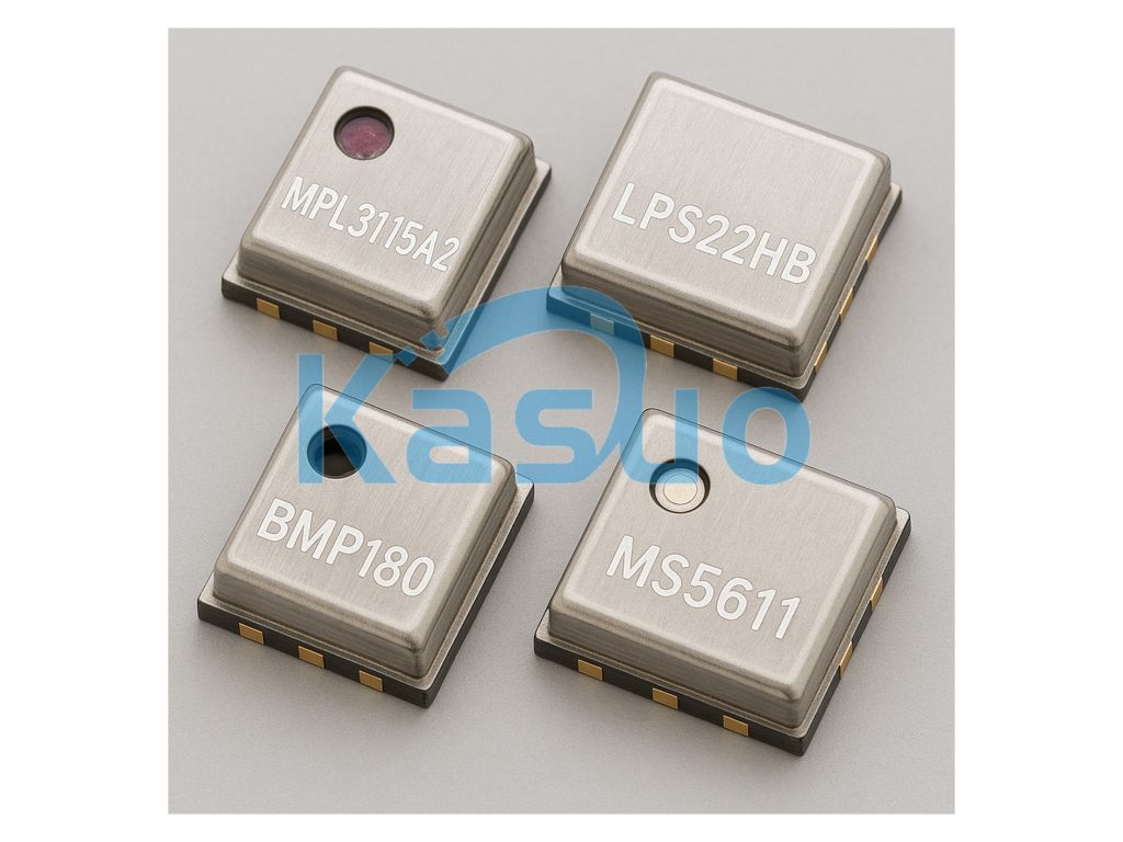
Mpl3115a2 Equivalent Sensor
| Parameters | MPL3115A2 | LPS22HB | BMP180 | MS5611 |
|---|---|---|---|---|
| Sensor Type | Pressure + Temperature Sensor | Pressure + Temperature Sensor | Pressure + Temperature Sensor | Pressure Sensor |
| Pressure Range | 20 to 110 kPa | 260 to 1260 hPa | 300 to 1100 hPa | 10 to 1200 mbar |
| Resolution | 1 Pa | 1 hPa | 0.03 hPa | 0.02 hPa |
| Temperature Range | -40°C to 85°C | -40°C to 85°C | -40°C to 85°C | -40°C to 85°C |
| Output Interface | I2C / SPI | I2C | I2C | I2C |
| Power Consumption | 3.3 µA | 2.5 µA | 3 µA | 1.5 µA |
| Précision | Pressure ±0.5 hPa, Temperature ±1°C | Pressure ±0.1 hPa, Temperature ±1°C | Pressure ±0.03 hPa, Temperature ±1°C | Pressure ±0.02 hPa, Temperature ±1°C |
| Type de colis | QFN (3x3mm) | LGA (3x3mm) | LGA (3.6×3.8mm) | LGA (3.3×3.8mm) |
When looking for a replacement for the MPL3115A2, the LPS22HB is a solid option. It offers similar temperature and pressure ranges, but with better pressure accuracy (±0.1 hPa). However, keep in mind that it only supports I2C, whereas the MPL3115A2 offers both I2C and SPI.
Another choice is the BMP180, which is a low-power sensor with high resolution and accuracy, making it perfect for applications sensitive to pressure and temperature changes. The downside is that it only supports I2C, and its pressure range is a bit narrower than the MPL3115A2.
If precision is your top priority, the MS5611 is a great option. It’s designed for high-precision pressure measurements, particularly in environments with large pressure variations. It consumes less power than the MPL3115A2, but keep in mind it only supports I2C communication.
Just make sure the replacement matches your project’s specific needs in terms of power, communication interface, and measurement range.
Mpl3115a2 Barometric Pressure Sensor Circuit

When you’re setting up the MPL3115A2, make sure to pay attention to the power supply. VDD (Pin 1) is where you’ll connect the positive voltage, usually between 1.95V and 3.6V. To keep the power stable, it’s a good idea to add two decoupling capacitors: a 100nF for high-frequency noise and a 10µF for smoothing out low-frequency fluctuations.
GND (Pin 2) is the ground pin, which you’ll connect to the system’s ground. VDDIO (Pin 4) powers the sensor’s logic, typically connected to the same voltage as VDD to keep things consistent.
For communication, SCL (Pin 8) and SDA (Pin 7) are your I2C lines. SCL is the clock signal, and SDA carries the data. Don’t forget the interrupt pins (INT1 and INT2) on Pins 5 and 6; they let you know when the sensor is ready with new data.
Lastly, ensure you have good decoupling to reduce power noise and keep everything running smoothly!
Mpl3115a2 Arduino Wiring Example

In this wiring setup, you’re connecting the MPL3115A2 barometric pressure sensor to an Arduino (with an Ethernet shield). Here’s how the connections work:
-
VDD (Pin 1) goes to the 5 V pin on the Arduino to power up the sensor.
-
GND (Pin 2) is connected to GND on the Arduino, completing the circuit.
-
SCL (Pin 8) connects to the SCL pin on the Arduino. On older boards, this is A5, but newer boards may have a dedicated SCL pin.
-
SDA (Pin 7) connects to the SDA pin on the Arduino. On older boards, it’s A4, but newer ones might have a dedicated SDA pin.
Le INT1 and INT2 pins are not connected here, as they’re optional depending on whether you need interrupt functionality for your project.
Once everything is hooked up, make sure you have the right I2C library in the Arduino IDE to start reading pressure and temperature data from the sensor.
Mpl3115a2 With Esp32 Tutorial
To get your MPL3115A2 barometric pressure sensor working with the ESP32, it’s pretty straightforward. First, you’ll connect the VDD of the sensor to the 5 V on the ESP32 for power, and the GND to ground. For communication, hook up the SCL pin from the sensor to GPIO 22 (the SCL pin on the ESP32) and SDA to GPIO 21 (the SDA pin). The INT1 et INT2 pins aren’t necessary for basic readings, so you can leave those disconnected unless you want to use interrupts.
Once you’ve got everything wired up, you’ll need to set up the Arduino IDE to work with the ESP32. Install the ESP32 board package, then the MPL3115A2 library. After that, upload the code to your ESP32, and open the Serial Monitor to see real-time pressure and temperature readings coming from your sensor.
If you run into issues with I2C communication, double-check the wiring and make sure you’re using the correct pins for SDA and SCL on your ESP32.
Plus comme ça

MT9V022IA7ATM-DR
sursemi

MT9V022IA7ATC-DR
sursemi
AR0331SRSC00XUEE0-DPBR
sursemi
AR0132AT6R00XPEA0-DPBR
sursemi
AR0132AT6M00XPEA0-DPBR
sursemi
AR0132AT6R00XPEA0-TPBR
sursemi
AR0132AT6C00XPEA0-TPBR
sursemi
MT9V127IA3XTC-DR
sursemi

AR0521SR2M09SURA0-DR
sursemi
MT9V024IA7XTM-TP
sursemi
AR0331SRSC00SUCA0-DPBR
sursemi
AR0331SRSC00XUEE0-DRBR
sursemi
Ajouter également au panier
DRV5057A4QLPGM
Texas Instruments

52.1-AN-10-2
J.W. Winco

MC05AH
Sensata-Cynergy3

455-00104
Laird Connectivité Inc.

55140-2H-05-A
Littelfuse Inc.

ABS3150
MAG-MATE®

M11/M5
Standex-Meder Electronics

MMF403929
Micro-Measurements (Division of Vishay Precision Group)

AIS1120SXTR
STMicroelectronics
TSOP34840SS1S
Division Optique Vishay Semiconductor

0729-1751-99
La société Fredericks

PS-SWX-103-GY
SensorWORX
Produits connexes
MT9V022IA7ATM-DR
sursemi
MT9V022IA7ATC-DR
sursemi
AR0331SRSC00XUEE0-DPBR
sursemi
AR0132AT6R00XPEA0-DPBR
sursemi
AR0132AT6M00XPEA0-DPBR
sursemi
AR0132AT6R00XPEA0-TPBR
sursemi
AR0132AT6C00XPEA0-TPBR
sursemi
MT9V127IA3XTC-DR
sursemi
AR0521SR2M09SURA0-DR
sursemi
MT9V024IA7XTM-TP
sursemi
AR0331SRSC00SUCA0-DPBR
sursemi
AR0331SRSC00XUEE0-DRBR
sursemi
AR0521SR2M09SURA0-DR1
sursemi
AR0144ATSM20XUEA0-TPBR
sursemi
AR0522SRSM09SURA0-DP
sursemi
AR0522SRSC09SURA0-DP
sursemi
MT9V034C12STM-DR1
sursemi
AR0132AT6R00XPEA0-TRBR
sursemi
AR0132AT6R00XPEA0-DRBR
sursemi
AR0132AT6M00XPEA0-DRBR
sursemi
AR0132AT6C00XPEA0-TRBR
sursemi
KAF-1001-AAA-CP-B1
sursemi
KAF-1001-AAA-CB-B2
sursemi
KAF-09000-ABA-DP-BA
sursemi
KAF-09000-ABA-DD-BA
sursemi

KAF-0402-ABA-CP-B2
sursemi
AR0331SRSC00SHCA0-DRBR
sursemi
MLX75023STF-BAB-001-TR
Melexis Technologies NV
AR0522SRSM09SURA0-DR
sursemi
AR0522SRSC09SURA0-DR
sursemi
Veuillez envoyer une demande de devis, nous vous répondrons immédiatement.
