Discover the versatility of the BPW34 with our comprehensive Reference Manual. Explore its applications in Arduino projects, circuit designs, and as a photodiode, solar cell, or radiation detector. Find detailed pinout information and pricing for this reliable component.
The BPW34 photodiode is great if you’re measuring ambient light or receiving infrared signals. It covers a wide wavelength range from visible to near-infrared (about 400nm–1100nm), especially sensitive around 900nm—perfect for infrared remote control, laser ranging, or simple light detection.
Its transparent plastic packaging allows good light penetration, giving it a fast response. With a reverse bias, its output remains linear, making ADC sampling straightforward and easy without complicated circuits.
Simply put, BPW34 is an excellent component for your light-sensing projects, performing especially well in low-light conditions.
BPW34 Pinout Polarity
पिन नंबर
पिन नाम
Polarity
विवरण
1
एनोड (+)
सकारात्मक
Connects to power supply positive or pull-up resistor
2
Cathode (−)
Negative / Output
Typically connects to ADC or amplifier
When using the BPW34 photodiode, always remember to connect it with the correct polarity. The anode goes to the positive voltage supply, and the cathode connects to ground through a resistor.
Adding a reverse bias (like 5V to the anode and resistor to ground at the cathode) boosts sensitivity and response speed, giving you clearer, linear readings.
Be cautious: prolonged direct exposure to intense light or lasers might damage the diode. It’s wise to add a protective housing or a filter.
Also, when soldering, work quickly and carefully—the transparent TO-18 or T-1¾ package can easily overheat if you’re not careful.
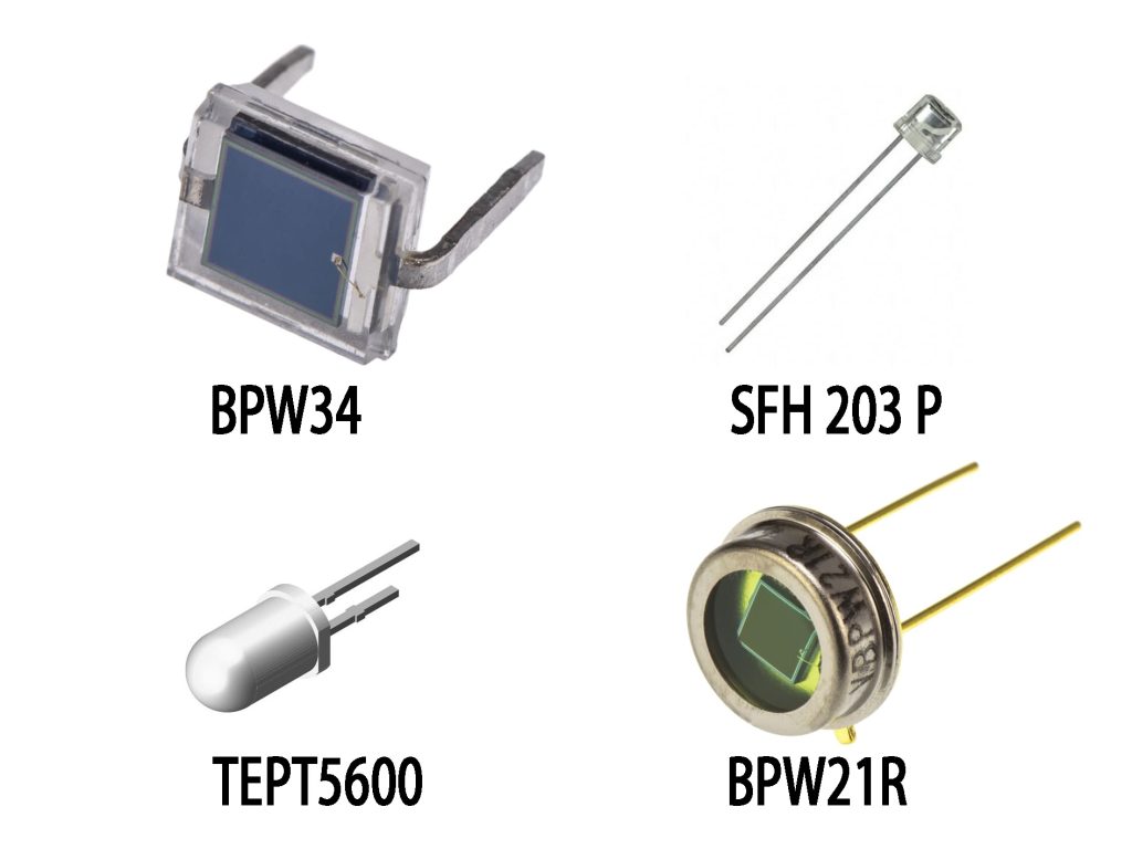
If you don’t have a BPW34 on hand, the SFH 203 P is your best bet—it’s almost identical in packaging, spectral sensitivity, and response speed, so you won’t need to modify your circuit at all.
The TEPT5600 looks similar but is optimized for visible light (peak sensitivity in green), making it great for ambient light sensing. However, it isn’t suitable for infrared remote control or laser detection applications.
The BPW21R is a more advanced photodiode with a metal TO-5 package and wider spectral response, ideal for industrial or high-precision setups. If you’re okay with changing the package layout slightly, it’s worth considering.
BPW34 Light Detection Circuit Example
If you’re measuring light intensity with the BPW34 photodiode, this circuit is exactly what you need. The BPW34 diode connects with reverse bias—the anode to ground, cathode to the TLC271 op-amp’s negative input.
The op-amp is crucial here, converting the tiny current from the BPW34 into a usable voltage signal (this setup is called a transimpedance amplifier). Adjusting resistor R4 (10kΩ) sets the gain—higher resistance means higher gain. Potentiometer R3 (500Ω) helps you fine-tune the output offset, ensuring accuracy.
You can feed the output voltage directly into your Arduino or microcontroller’s ADC pin to easily measure the light intensity. Remember, pick an op-amp with low input bias current (such as TLC271 or OPA129) to prevent noise from drowning your signal.
Overall, it’s a simple, reliable circuit perfect for ambient light sensing, laser detection, or IR projects.
BPW34 IR Receiver Circuit
If you’re looking to quickly set up a simple light-sensing circuit with the BPW34 diode, here’s an easy method. Connect the BPW34’s anode to ground, and its cathode to the midpoint of a 1MΩ potentiometer. With the potentiometer connected between +5V and ground, you can easily set the bias voltage.
The working principle is straightforward: as ambient infrared or visible light intensity increases, the BPW34’s photocurrent pulls the cathode voltage down, allowing you to detect changes in light levels. By adjusting the potentiometer, you can fine-tune sensitivity and set trigger thresholds easily.
This circuit is perfect for simple projects like IR receiver front-ends, optical gates, or basic laser detection setups. Just remember, since the output signal is quite small, you’ll probably want to follow it with an ADC or amplifier circuit for better processing.
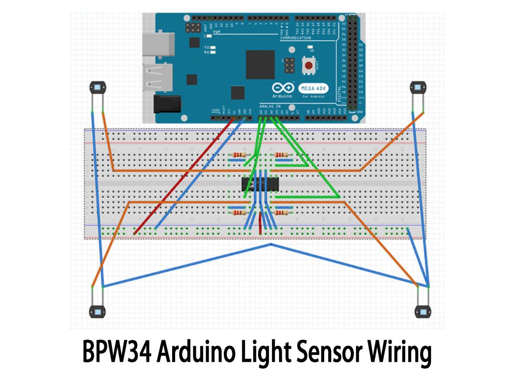
BPW34 Arduino Light Sensor Wiring
If you’re looking to build an easy light direction sensor or obstacle detector with Arduino and BPW34 photodiodes, this setup is perfect for you. Simply take four BPW34 diodes, connect all their anodes to ground, and hook each cathode to Arduino’s analog inputs (A0–A3) through individual resistors. The other side of each resistor goes to 5V, forming a voltage divider. Stronger incoming light means more noticeable voltage changes at the Arduino input.
You can easily read the light intensity of each direction using Arduino’s analogRead() function. For instance, if the left diode receives brighter light, its output voltage clearly changes, and your code can easily detect the direction.
For higher accuracy, you might add an operational amplifier or filters. It’s great for DIY projects like light-following robots, laser tracking, or simple optical alarms.
BPW34 Application
The BPW34 diode is super versatile for DIY optical projects. For example, pair it with an amplifier and demodulator, and you have a simple IR remote receiver for home appliances. Or build an ambient light sensor to automatically adjust screen brightness or street lighting.
For cooler projects, combine it with a laser module for distance measurement, beam detection, or security alarms. You can even measure sunlight intensity to create your own solar tracking or daily sunshine recorder.
If you’re into robotics, pair it with IR LEDs for obstacle avoidance or set it up with an optical encoder disc for precise positioning.