ESP32-S3FN8 डेटाशीट, मूल्य, पीडीएफ
- प्रकार: टीएक्सआरएक्स + एमसीयू
- शिष्टाचार: 802.11b/g/n, Bluetooth v5.0
- सीरियल इंटरफेस: I2C, I2S, SPI, UART, USB
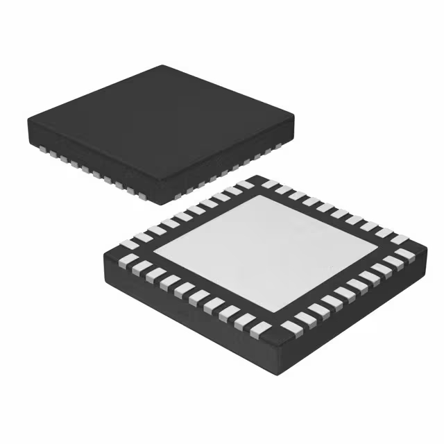
- पैकेट: 56-VFQFN एक्सपोज़्ड पैड

HK$250.00 से अधिक ऑर्डर पर निःशुल्क डिलीवरी

त्वरित प्रतिक्रिया, त्वरित उद्धरण

फ्लैश शिपमेंट, बिक्री के बाद कोई चिंता नहीं

मूल चैनल, प्रामाणिक उत्पादों की गारंटी
Key Features of the ESP32-S3FN8
The ESP32-S3FN8 is a powerful, energy-efficient microcontroller designed for a wide range of applications, including IoT, wearables, and smart devices. It features a dual-core processor with a clock speed of up to 240 MHz, ensuring fast and reliable performance. With integrated Wi-Fi and Bluetooth LE connectivity, the ESP32-S3FN8 is perfect for projects requiring wireless communication. It also offers advanced features like AI acceleration, making it ideal for edge computing applications. The chip is equipped with multiple I/O options, including SPI, UART, I2C, and PWM, providing flexibility for various peripheral connections. Compact and feature-rich, the ESP32-S3FN8 is a great choice for high-performance embedded systems.
ESP32-S3FN8 Pinout
| पिन नंबर | पिन नाम | विवरण |
|---|---|---|
| 1 | GPIO1 | General Purpose Input/Output pin. Can be used for digital input or output. |
| 2 | GPIO2 | Another GPIO pin, used for digital input/output. Often used for debugging. |
| 3 | GPIO3 | Similar to GPIO1 and GPIO2, commonly used for additional I/O or UART. |
| 4 | 3V3 | 3.3V power supply pin. Powers the ESP32-S3FN8 module. |
| 5 | जीएनडी | Ground pin. Connect this to the system ground for proper operation. |
| 6 | EN | Enable pin. Used to wake up the chip from deep sleep or reset it. |
| 7 | RXD0 | UART0 receive data pin. Used for serial communication with a microcontroller. |
| 8 | TXD0 | UART0 transmit data pin. Used for serial communication with a microcontroller. |
| 9 | SD2 | SD card data line 2 pin, used for SD card interface. |
| 10 | SD3 | SD card data line 3 pin, used for SD card interface. |
Pinout Usage and Notes
The ESP32-S3FN8 has flexible I/O options, making it perfect for various applications. The GPIO pins (1, 2, 3) can be configured as digital inputs or outputs, depending on your needs. For serial communication, the RXD0 and TXD0 pins are used for UART communication. If you plan to use an SD card, pins SD2 and SD3 are dedicated for the data lines. Make sure to properly connect the 3V3 and GND pins to supply power and ensure stable operation. When using the EN pin, it allows you to reset the module or wake it up from deep sleep. Always consult the datasheet for detailed configuration options to optimize your design.
ESP32-S3FN8 Equivalent Models
| नमूना | CPU | याद | Wireless Connectivity | Flash Memory | पैकेज का प्रकार | Key Features |
|---|---|---|---|---|---|---|
| ESP32-S3FN8 | Dual-core | 512KB SRAM | Wi-Fi 802.11 b/g/n, Bluetooth LE | 8MB | QFN-38 | AI acceleration, multiple I/O options |
| ESP32-WROOM-32 | Dual-core | 520KB SRAM | Wi-Fi 802.11 b/g/n, Bluetooth 4.2 | 4MB | QFN-38 | Broad compatibility, popular for IoT |
| ESP32-S2 | Single-core | 320KB SRAM | Wi-Fi 802.11 b/g/n | 4MB | QFN-36 | Lower power, great for simple IoT projects |
| ESP32-C3 | RISC-V core | 400KB SRAM | Wi-Fi 802.11 b/g/n, Bluetooth LE | 4MB | क्यूएफएन-32 | Low power, RISC-V architecture |
Equivalent Models Usage and Notes
If you need an alternative to the ESP32-S3FN8, models like the ESP32-WROOM-32, ESP32-S2, and ESP32-C3 can also meet your needs. The ESP32-WROOM-32 offers similar dual-core performance but has less SRAM and no AI acceleration. The ESP32-S2 is a single-core option with less memory but is great for lower-power applications. If you’re looking for an affordable, low-power solution with RISC-V architecture, the ESP32-C3 is a solid choice. When choosing an alternative, consider your project’s need for AI acceleration, memory size, and wireless connectivity options to select the most fitting replacement.
Choosing the Right ESP32 Model for Your Project
When deciding on an ESP32 module, it’s important to match your project’s needs with the right specs. The ESP32-S3FN8 is ideal if you need dual-core performance with AI acceleration, making it great for more complex IoT applications. However, if you’re working on a simpler project, models like the ESP32-S2 or ESP32-C3 offer lower power consumption with fewer resources, which can be perfect for basic IoT tasks. The ESP32-WROOM-32 is another versatile option, providing broad compatibility with a good balance of features. Choose the model that fits your performance, power, and connectivity needs for optimal results.
ESP32-S3FN8 Circuit Diagram and Analysis
The ESP32-S3FN8 is a versatile microcontroller designed for various applications, including IoT devices, wearables, and smart home systems. While specific circuit diagrams for this model may not be readily available, understanding its typical application and power requirements is essential for effective integration.
Key Components and Connections
-
Power Supply: The ESP32-S3FN8 operates at a voltage range of 3.0V to 3.6V. It’s crucial to provide a stable 3.3V power supply to ensure proper functionality. Decoupling capacitors (e.g., 0.1µF and 10µF) should be placed near the power pins to filter out noise and stabilize the voltage.
-
Clock Source: An external 40MHz crystal oscillator is required for the main system clock. The load capacitance (C_L) for the crystal can be calculated using the formula:
Where और are the external capacitors, and is the stray capacitance of the PCB. Adjusting these values ensures the crystal operates within the desired frequency tolerance.
-
RTC Power Supply: The VDD3P3_RTC pin powers the Real-Time Clock (RTC) and analog circuitry. It’s recommended to place a 0.1µF decoupling capacitor near this pin to maintain stable operation. Note that this power supply cannot be used as a single backup power source.
-
Reset and Enable: The CHIP_PU pin is used to enable or reset the chip. Ensure proper timing when asserting this pin to avoid unintended resets or power-up issues.
Usage Notes
-
Power Management: Ensure that the power supply can handle the peak current demands of the ESP32-S3FN8, especially during Wi-Fi or Bluetooth transmissions.
-
PCB Layout: Maintain a solid ground plane and minimize the length of high-speed signal traces to reduce electromagnetic interference (EMI) and signal integrity issues.
-
Component Placement: Place decoupling capacitors as close as possible to the power pins of the ESP32-S3FN8 to effectively filter out noise.
For more detailed information and specific circuit examples, refer to the ESP32-S3 Hardware Design Guidelines.


