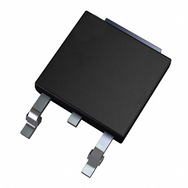
आईआरएफ3710 datasheet, pinout, price & circuit
- ट्रांजिस्टर प्रकार: 1 एन-चैनल
- सामान्य टर्न-ऑफ विलंब समय: 45 ns
- सामान्यतः चालू होने में विलंब का समय: 12 ns
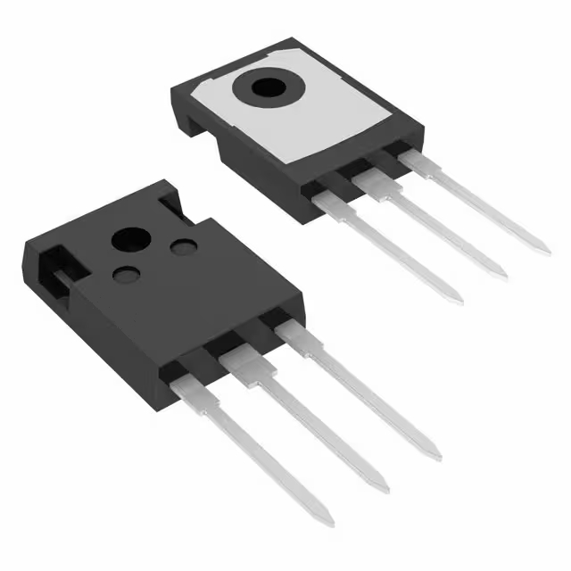
- पैकेट: टीओ-220-3

HK$250.00 से अधिक ऑर्डर पर निःशुल्क डिलीवरी

त्वरित प्रतिक्रिया, त्वरित उद्धरण

फ्लैश शिपमेंट, बिक्री के बाद कोई चिंता नहीं

मूल चैनल, प्रामाणिक उत्पादों की गारंटी
Key Features of the IRF3710
The IRF3710 is a high-performance N-channel MOSFET known for its excellent switching capabilities and low on-resistance. It is commonly used in power management systems, including DC-DC converters and motor control circuits. With a maximum drain-to-source voltage of 55V and a high current rating, the IRF3710 can handle demanding applications with ease. Its low Rds(on) helps improve efficiency by reducing power loss. The MOSFET also features fast switching speeds, making it ideal for high-frequency applications. Whether you’re designing for power supplies or energy-efficient systems, the IRF3710 provides reliable performance and efficiency.
IRF3710 Pinout
| पिन नंबर | पिन नाम | विवरण |
|---|---|---|
| 1 | दरवाज़ा | The gate controls the switching of the MOSFET. A voltage applied here turns the MOSFET on or off. |
| 2 | नाली | The drain pin connects to the load side of the circuit. It carries the current from the source to the load. |
| 3 | स्रोत | The source pin connects to the negative side of the circuit, typically to ground in N-channel MOSFETs. |
Pinout Usage and Notes
The IRF3710 MOSFET is an N-channel device, and its gate controls the flow of current between the source and drain. When a positive voltage is applied to the gate, it allows current to flow from the source to the drain. To ensure proper operation, the source should be connected to the negative rail of the circuit. It’s important to properly manage the gate voltage to prevent unnecessary power consumption and overheating. Proper heatsinking is also recommended, as this MOSFET can dissipate significant power.
IRF3710 Equivalent Models
| नमूना | Vds (Max) | Id (Max) | Rds(on) | Gate Charge | पैकेज का प्रकार |
|---|---|---|---|---|---|
| आईआरएफ3710 | 55 वी | 62A | 0.008Ω | 140nC | को-220 |
| IRLZ44N | 55 वी | 47A | 0.022Ω | 67nC | को-220 |
| IRL540N | 55 वी | 36A | 0.077Ω | 50nC | को-220 |
| STP75NF75 | 75V | 80A | 0.008Ω | 200nC | को-220 |
Equivalent Models Usage and Notes
If you’re looking for alternatives to the IRF3710, the IRLZ44N, IRL540N, and STP75NF75 are good replacements. These models offer similar voltage and current ratings, making them suitable for most power applications. The IRLZ44N and IRL540N have slightly higher Rds(on) values, which could lead to more power loss in some designs. However, they can still be used in lower-power applications where efficiency isn’t as critical. The STP75NF75 offers a higher voltage rating and similar on-resistance but with a larger gate charge, so it may not be ideal for high-speed switching. Always check the specific requirements for your application to ensure the replacement is a good fit.
IRF3710 with Arduino
The IRF3710 is a great choice for controlling high-power devices with an Arduino. It can be used in various applications like motor control, power supplies, and other circuits that require switching high currents. To control the IRF3710 with an Arduino, simply connect the gate to one of the Arduino’s digital pins through a resistor. This allows the Arduino to control the MOSFET, turning it on and off based on the logic level sent from the microcontroller. Remember to use a suitable heat sink for the MOSFET, as it may generate heat when handling high currents.
IRF3710 Price
The IRF3710 is available at competitive prices, making it an affordable option for power applications. Prices typically range from $1 to $3, depending on the distributor and order volume. It’s worth checking multiple sources for the best price and availability, especially if you’re purchasing in bulk for larger projects. Always consider the cost of shipping and any additional fees when calculating the total price.
IRF3710 MOSFET Application Circuit
The IRF3710 is an N-channel MOSFET commonly used in power applications such as motor control, power supplies, and switching regulators. A typical application circuit includes the MOSFET connected in a low-side switch configuration, where the source is connected to ground, the drain to the load, and the gate is driven by a control signal. A resistor is often placed between the gate and the control signal to limit the gate charging current and prevent damage. Additionally, a flyback diode is placed across the load to protect the MOSFET from voltage spikes caused by inductive loads. Proper heat sinking is essential to dissipate the power loss and maintain safe operating temperatures.
Circuit Analysis
In this configuration, when a positive voltage is applied to the gate relative to the source, the MOSFET turns on, allowing current to flow from the drain to the source through the load. The flyback diode provides a path for the current when the MOSFET turns off, preventing high-voltage spikes that could damage the MOSFET. The gate resistor controls the switching speed, balancing between fast switching and minimizing electromagnetic interference. The heat sink is necessary to manage the power dissipation, which is a function of the voltage drop across the MOSFET and the current flowing through it.
Usage Notes
-
Gate Drive Voltage: Ensure the gate voltage is within the specified range to fully turn on the MOSFET and minimize on-resistance.
-
Gate Resistor: Select an appropriate value to control the switching speed and reduce noise.
-
Flyback Diode: Use a diode with suitable voltage and current ratings to protect the MOSFET from inductive kickbacks.
-
Heat Management: Adequate heat sinking is crucial to prevent thermal damage to the MOSFET.
-
PCB Layout: Design the PCB with short, wide traces for high-current paths to minimize voltage drops and inductance.
For more detailed information and specific circuit diagrams, refer to the IRF3710 datasheet.


