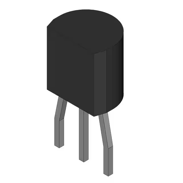
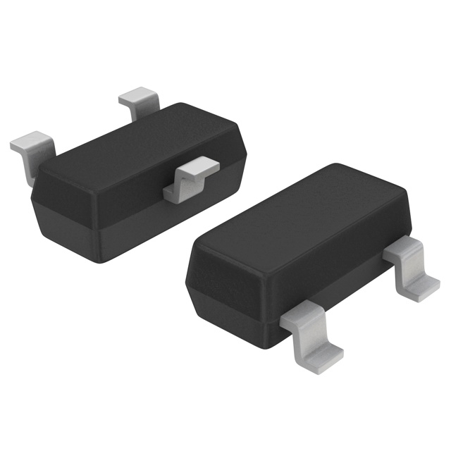
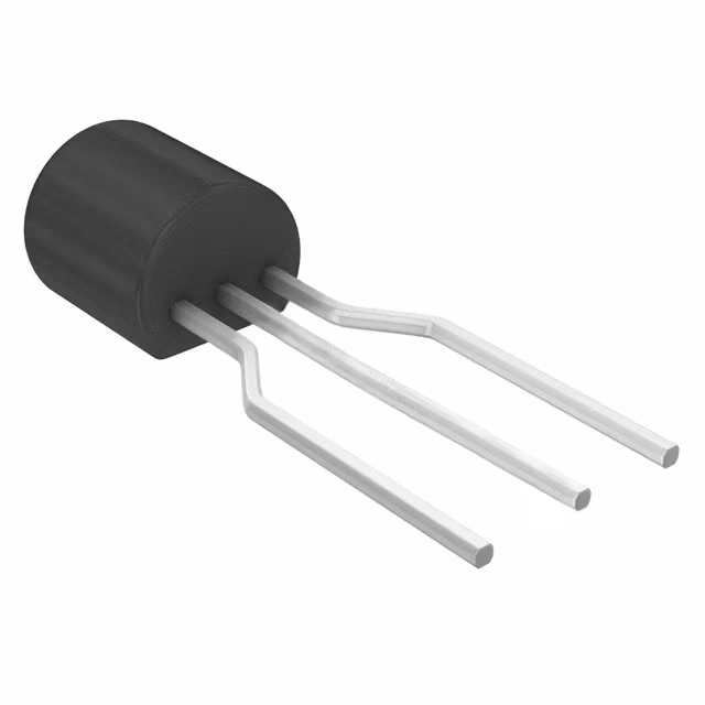
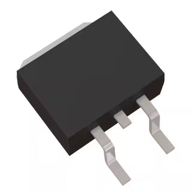
IRFP260N datasheet, circuit, equivalent, pinout
- ट्रांजिस्टर प्रकार: 1 एन-चैनल
- सामान्य टर्न-ऑफ विलंब समय: 55 ns
- सामान्यतः चालू होने में विलंब का समय: 17 ns
- पैकेट: -

HK$250.00 से अधिक ऑर्डर पर निःशुल्क डिलीवरी

त्वरित प्रतिक्रिया, त्वरित उद्धरण

फ्लैश शिपमेंट, बिक्री के बाद कोई चिंता नहीं

मूल चैनल, प्रामाणिक उत्पादों की गारंटी
Key Features of the IRFP260 MOSFET
The IRFP260 is a powerful N-channel MOSFET designed for high-speed switching and power applications. With a maximum drain-to-source voltage of 200V and a continuous drain current of up to 50A, it’s built to handle significant power loads efficiently. The low RDS(on) (drain-to-source resistance) ensures minimal power loss during operation, making it ideal for use in power supplies, motor drives, and other high-performance circuits. The IRFP260 is known for its reliability in switching and is commonly used in automotive, industrial, and renewable energy applications, where high current handling and low power dissipation are essential.
IRFP260 Pinout
| नत्थी करना | Label | विवरण |
|---|---|---|
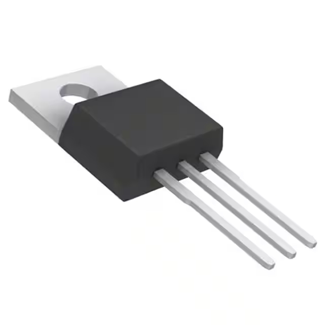
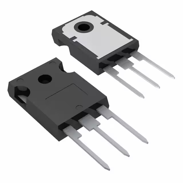
| 1 | Gate (G) | The gate terminal, used to control the switching of the MOSFET. Apply voltage to turn it on/off. |
| 2 | Drain (D) | The drain terminal, where the load is connected. This is the output of the MOSFET. |
| 3 | Source (S) | The source terminal, typically connected to the ground or negative side of the power supply. |
Using the IRFP260 Pinout
The IRFP260 is an N-channel MOSFET, and its operation is controlled via the दरवाज़ा (Pin 1). To turn the MOSFET on, apply a positive voltage to the gate relative to the source. The नाली (Pin 2) is where the load is connected, and the स्रोत (Pin 3) is typically connected to the negative side of the circuit. Make sure the voltage applied to the gate is sufficient to fully turn on the MOSFET, and avoid exceeding the maximum gate-to-source voltage to prevent damage. Proper heat dissipation is crucial, especially when switching high currents.
IRFP260 Equivalent Models
Here’s a comparison of equivalent N-channel MOSFETs with similar packaging and features:
| नमूना | Voltage Rating | Current Rating | RDS(on) | पैकेज का प्रकार | Key Features |
|---|---|---|---|---|---|
| IRFP260 | 200 वोल्ट | 50A | 0.06Ω | को-220 | High power, low RDS(on), ideal for power supplies and motor control |
| आईआरएफपी450 | 500V | 40ए | 0.022Ω | को-220 | Higher voltage, lower RDS(on), used in high-voltage applications |
| IRFP360 | 200 वोल्ट | 40ए | 0.08Ω | को-220 | Similar voltage rating, but higher RDS(on), good for lower current applications |
| STP75NF75 | 75V | 80A | 0.005Ω | को-220 | Low RDS(on), ideal for high current, but lower voltage rating |
Substitution Tips
When replacing the IRFP260, make sure to match key parameters like the voltage rating, current rating, and RDS(on). For example, the आईआरएफपी450 offers a higher voltage rating (500V) and a lower RDS(on), making it suitable for high-voltage applications. The IRFP360 is a good alternative with similar voltage but higher RDS(on), ideal for circuits that don’t require as low a resistance. If you’re dealing with higher current demands, the STP75NF75 offers a very low RDS(on) but comes with a lower voltage rating. Always ensure the package type और voltage rating align with your design needs to prevent any performance issues.
IRFP260 Circuit Induction
The IRFP260 MOSFET is commonly used in high-power circuits like inductive load drivers, where efficient switching and low power dissipation are key. In these circuits, the IRFP260 is typically used to control current flow through inductive loads such as motors, solenoids, or relays. The MOSFET’s low RDS(on) ensures minimal heat generation during operation, while its ability to handle high current and voltage makes it ideal for these applications. To protect the IRFP260 from voltage spikes caused by the inductive load, it’s important to use flyback diodes across the load to safely redirect excess energy. This setup ensures reliable and efficient switching, minimizing wear and tear on the components.
IRFP260 Circuit Diagram and Analysis
The IRFP260 is a robust N-channel MOSFET widely used in high-power applications such as audio amplifiers, induction heaters, and power supplies. Below is a simplified circuit diagram illustrating its typical application in a 1000W MOSFET amplifier:
Circuit Components and Functionality
-
IRFP260 MOSFETs: These are used in the output stage to amplify the signal.
-
Driver Transistors (e.g., MJE15034, MJE15035): These transistors provide the necessary current to switch the MOSFETs on and off.
-
Pre-Amplifier Stage: Includes components like MJE340, MJE350, and 2N5401 to boost the input signal to a level suitable for the driver stage.
-
Gate Resistors: Limit the gate charging current and control the switching speed of the MOSFETs.
-
Flyback Diodes: Protect the MOSFETs from voltage spikes caused by inductive loads.
-
Power Supply: Typically a ±60V DC supply to provide the necessary voltage for the amplifier.
Operation Overview
In this circuit, the input audio signal is first amplified by the pre-amplifier stage. The driver transistors then receive this signal and provide the necessary current to switch the IRFP260 MOSFETs. The MOSFETs amplify the signal to a level suitable for driving speakers. Flyback diodes are used to protect the MOSFETs from voltage spikes caused by the inductive nature of the speakers.
Key Considerations
-
Heat Dissipation: Ensure adequate cooling for the MOSFETs, as they can dissipate significant power.
-
Gate Drive: Proper gate drive is essential for efficient switching.
-
Component Ratings: Use components with ratings suitable for the operating conditions to ensure reliability and safety.



.jpg)
