
एनआरएफ24एल01 alcance | pinout
- ब्रांड: नॉर्डिक सेमीकंडक्टर एएसए
- डाउनलोड करना: NRF24L01 Datasheet PDF
- कीमत: जाँच करना
- स्टॉक में: 4,008
- प्रकार: केवल TxRx
- आरएफफैमिली/स्टैंडर्ड: सामान्य ISM > 1GHz
- शिष्टाचार: -
- पैकेट: 20-VFQFN एक्सपोज़्ड पैड


HK$250.00 से अधिक ऑर्डर पर निःशुल्क डिलीवरी

त्वरित प्रतिक्रिया, त्वरित उद्धरण

फ्लैश शिपमेंट, बिक्री के बाद कोई चिंता नहीं

मूल चैनल, प्रामाणिक उत्पादों की गारंटी
NRF24L01 Arduino Tutorial – Wireless Communication
एनआरएफ24एल01
The NRF24L01 is a popular wireless module made by Nordic Semiconductor, mainly used for short-range wireless communication. It’s known for being energy-efficient, inexpensive, and fast, making it a great choice for wireless remote-control devices and IoT applications.
Specifically, it operates on the 2.4GHz band, similar to your home’s Wi-Fi, and you don’t need special permissions or licenses to use this frequency. It can transmit data at speeds up to 2Mbps, which is usually more than enough for typical wireless data transfers. It runs easily on a low voltage of just 3.3V, and it’s very power-efficient, drawing almost no current in standby mode.
You’ll often find the NRF24L01 used in remote-controlled cars and drones, as well as smart-home gadgets and industrial IoT sensors. Its typical transmission range is dozens of meters, usually sufficient for most applications. And if you pair it with a better antenna, you can even increase the communication range significantly.
In short, the NRF24L01 is easy to use, affordable, and widely chosen for wireless projects.
NRF24L01 pinout
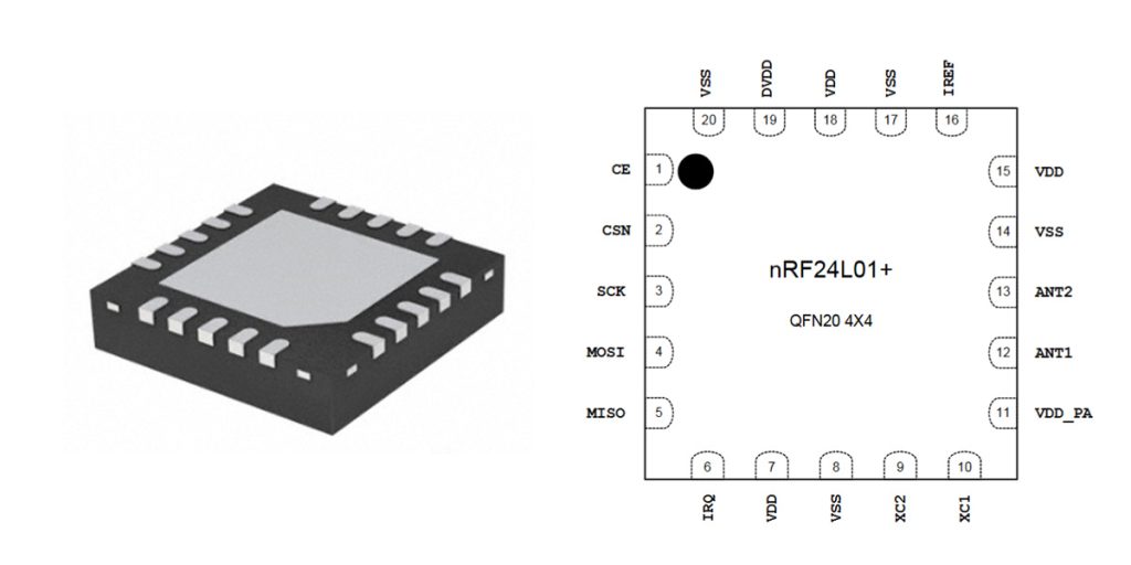
| नत्थी करना | नाम | Pin function | विवरण |
|---|---|---|---|
| 1 | CE | Digital Input | Chip Enable Activates RX or TX mode |
| 2 | CSN | Digital Input | SPI Chip Select |
| 3 | SCK | Digital Input | SPI Clock |
| 4 | MOSI | Digital Input | SPI Slave Data Input |
| 5 | MISO | Digital Output | SPI Slave Data Output, with tri-state option |
| 6 | IRQ | Digital Output | Maskable interrupt pin. Active low |
| 7 | वीडीडी | शक्ति | Power Supply (+1.9V – +3.6V DC) |
| 8 | VSS | शक्ति | ग्राउंड (0V) |
| 9 | XC2 | Analog Output | Crystal Pin 2 |
| 10 | XC1 | Analog Input | Crystal Pin 1 |
| 11 | VDD_PA | Power Output | Power Supply Output (+1.8V) for internal nRF24L01 Power Amplifier. Must be connected to ANT1 and ANT2 as shown in datasheet. |
| 12 | ANT1 | RF | Antenna interface 1 |
| 13 | ANT2 | RF | Antenna interface 2 |
| 14 | VSS | शक्ति | ग्राउंड (0V) |
| 15 | वीडीडी | शक्ति | Power Supply (+1.9V – +3.6V DC) |
| 16 | IREF | Analog Input | Reference current. Connect a 22kΩ resistor to ground. |
| 17 | VSS | शक्ति | ग्राउंड (0V) |
| 18 | वीडीडी | शक्ति | Power Supply (+1.9V – +3.6V DC) |
| 19 | DVDD | Power Output | Internal digital supply output for de-coupling purposes. |
| 20 | VSS | शक्ति | ग्राउंड (0V) |
For optimal performance, keep the wires short, especially on SPI lines, and consider placing a decoupling capacitor (0.1μF and 10μF) between VCC and GND pins to reduce power supply noise.
NRF24L01 equivalent module
| मॉड्यूल | उत्पादक | Frequency | Data Rate | Voltage Range | Range | इंटरफ़ेस | अनुकूलता |
|---|---|---|---|---|---|---|---|
| एनआरएफ24एल01 | Nordic | 2.4 GHz | 250kbps-2Mbps | 1.9-3.6V | ~100m (open area) | एसपीआई | – |
| RFM75 | HopeRF | 2.4 GHz | 250kbps-2Mbps | 1.9-3.6V | ~100m (open area) | एसपीआई | Pin compatible |
| SI24R1 | Nanjing Semi | 2.4 GHz | 250kbps-2Mbps | 1.9-3.6V | ~100m (open area) | एसपीआई | Pin compatible |
| LT8900 | Lontium | 2.4 GHz | 250kbps-1Mbps | 1.9-3.6V | ~100m (open area) | एसपीआई | Similar but requires minor software adjustments |
Summary and Selection Tips:
When choosing a replacement for the NRF24L01 module, it’s important to ensure pin compatibility (such as RFM75 and SI24R1, which are direct pin-compatible alternatives). Always verify voltage compatibility and SPI interface details. While modules like LT8900 have similar features, they might require minor software adjustments. Be mindful of the intended application—especially in terms of required range and data rate—to ensure optimal compatibility and performance.
NRF24L01 wireless communication circuit

This schematic shows a typical NRF24L01 wireless communication circuit, which is commonly used for short-range wireless data transfer.
Looking at the diagram, you’ll notice that the NRF24L01 chip communicates with a microcontroller or other control chip using an SPI interface (SCK, MOSI, MISO, CSN). There’s also a pin labeled “CE,” which controls when the module sends or receives data. Another pin, IRQ, isn’t used much but serves as an interrupt signal, informing the microcontroller when data transmission is complete.
Next to the NRF24L01 chip, there’s a 16 MHz crystal oscillator (JZ1) paired with two small 22pF capacitors (C6 and C7) to stabilize its frequency, and a 1MΩ resistor (R2) ensures the oscillator starts reliably.
Since the NRF24L01 needs a stable 3.3V power supply, the schematic includes several capacitors (C8, C9) to filter out noise and ensure clean power delivery, helping maintain the quality of the wireless signal.
On the antenna side, you’ll see inductors (L1, L2, L3) and capacitors (C3, C4, C5, C6). These components form what’s known as an RF matching network, which helps signals smoothly reach the antenna without significant losses or reflections. Simply put, it ensures the wireless signal is transmitted farther and more reliably.
NRF24L01 power supply issues
The एनआरएफ24एल01 wireless module is sensitive to power supply stability, and unstable or noisy power lines often cause communication problems. Issues commonly include intermittent connectivity, reduced range, or module resets. To avoid these issues, it’s highly recommended to:
-
Use a stable 3.3V power supply: The NRF24L01 strictly requires a stable voltage around 3.3V.
-
Add a decoupling capacitor: Connect a 10µF electrolytic capacitor directly between the VCC and GND pins on the module. This smooths out voltage fluctuations, ensuring reliable performance.
-
Ensure proper grounding: Poor grounding can introduce noise and instability.
इसी तरह और भी

N000900L006A
Cambium
NB-N500032A-GL
Cambium
N000000T001A
Cambium
85009325001
Cambium
N110082L141A
Cambium
N110082L145A
Cambium
C030045C001A
Cambium
C060082R084A
Cambium
C800082K003A
Cambium
MT-650-63
CommScope
C024045C002A
Cambium
N110082L131A
Cambium
कार्ट में भी जोड़ें
SME0618LI1CDQ
L3 Narda-MITEQ

CBA-EZTEMP-1
आरएफ समाधान
TCDRO-F-08425-ST
L3 Narda-MITEQ

QMC-WB28-SE90
Quantum Microwave Components
CER0254B
Tusonix a Subsidiary of CTS Electronic Components

ZX47-60-S+
मिनी सर्किट

D4I2021-2
DiTom Microwave
20953000019
हार्टिंग

FAR-D6JG-2G1400-D3FZ-Z
ताइयो युडेन

एलटीसी5541IUH#TRPBF
एनालॉग डिवाइसेज इंक.

EA-ACC-021
Embedded Artists

MAX2204EXK+T
एनालॉग डिवाइसेज इंक./मैक्सिम इंटीग्रेटेड
संबंधित उत्पाद
N000900L006A
Cambium
NB-N500032A-GL
Cambium
N000000T001A
Cambium
85009325001
Cambium
N110082L141A
Cambium
N110082L145A
Cambium
C030045C001A
Cambium
C060082R084A
Cambium
C800082K003A
Cambium
MT-650-63
CommScope
C024045C002A
Cambium
N110082L131A
Cambium
N110082L132A
Cambium
IP-20C_DC_CONN
Ceragon
N060082L136A
Cambium
C110082B056A
Cambium
N000065L001C
Cambium
DA-C200
CommScope
N110082L180A
Cambium
N000000T002A
Cambium

ANK-910M
Com-Power Corporation
ANK-910L
Com-Power Corporation
ANK-318
Com-Power Corporation
ANK-140
Com-Power Corporation
APF-5060
Com-Power Corporation
AMTTC-300
Com-Power Corporation
AT-812
Com-Power Corporation
ANK-310
Com-Power Corporation
AM-400A
Com-Power Corporation
AT-220
Com-Power Corporation
कृपया आरएफक्यू भेजें, हम तुरंत जवाब देंगे।
