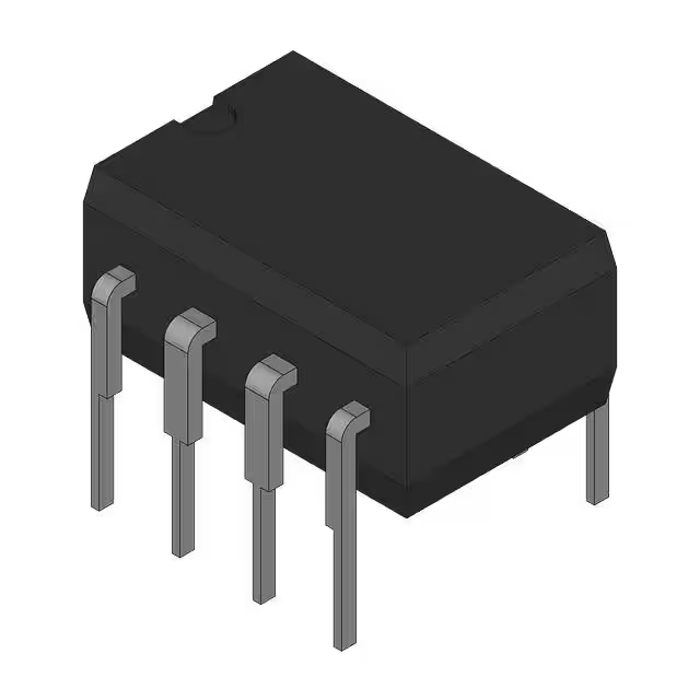
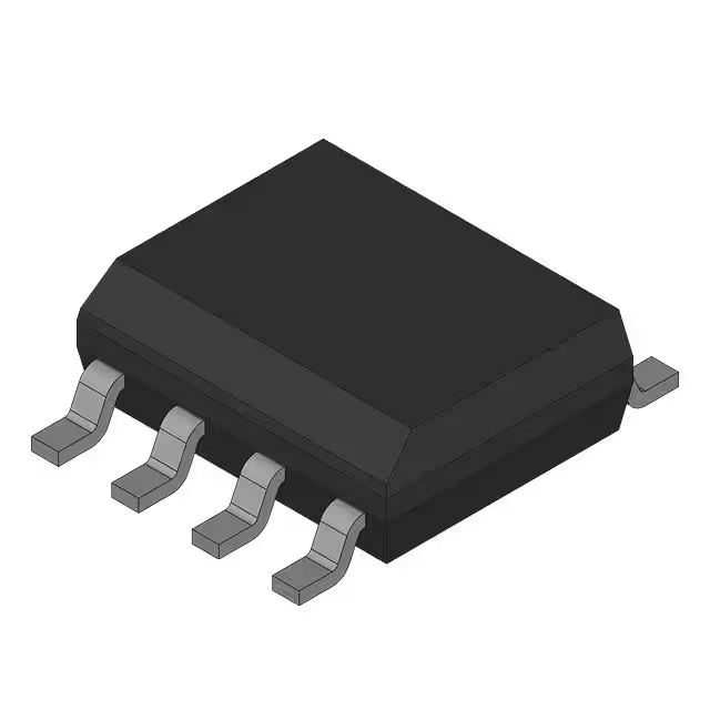
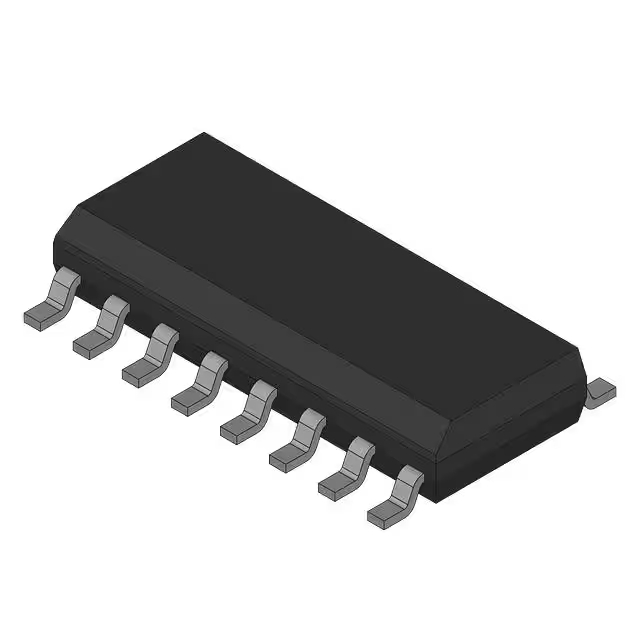
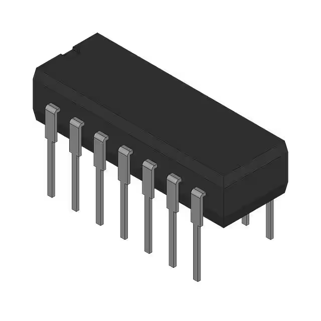
Sn65hvd230d
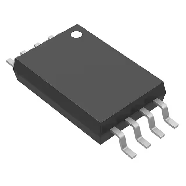
The SN65HVD230D from Texas Instruments is a differential signal driver designed for CAN bus communication, making it perfect for industries like automotive, industrial automation, and embedded systems. It offers several key features that make it reliable and efficient:
-
Low Power Consumption: It’s ideal for battery-powered systems, with a low-power standby mode that kicks in when no data is being transmitted.
-
High-Speed Data Transmission: It supports data rates up to 1 Mbps, making it great for fast CAN communication.
-
Wide Voltage Range: It operates between 4.5V to 5.5V, making it adaptable to various power supply voltages.
-
Robust Differential Signaling: It ensures stable data transmission, even in noisy environments.
-
Integrated Protection: With built-in current limiting and thermal shutdown, it’s designed for reliable and safe operation.
In short, the SN65HVD230D is a versatile, low-power CAN driver perfect for automotive, industrial, and embedded systems that require efficient and reliable communication.
Sn65hvd230d Pinout

| पिन नंबर |
पिन नाम |
Function Description |
| 1 |
CANH |
CAN bus differential signal high pin. |
| 2 |
CANL |
CAN bus differential signal low pin. |
| 3 |
VSS |
Ground pin, power supply negative. |
| 4 |
R0 |
Receiver data output pin, stores received data. |
| 5 |
R1 |
Receiver data output pin (R0 is connected), same as R0. |
| 6 |
वीसीसी |
Power supply input pin, works in the range of 4.5V to 5.5V. |
| 7 |
VREF |
Voltage reference pin, connects to the reference voltage. |
| 8 |
टीएक्सडी |
Transmit data pin, used to send data to the CAN bus. |
Here’s how to use the pins on the SN65HVD230D properly:
-
CANH and CANL: These are the core of the CAN bus. They carry differential signals and must be connected to the corresponding lines on the bus. If they’re not connected properly or if there’s a short between them, communication won’t work.
-
VSS and VCC: VSS is the ground pin, and it should be connected to the system’s ground. वीसीसी is the power input pin, usually connected to a 5 वी power supply. Make sure the voltage is stable—too high or low can damage the chip or cause malfunctions.
-
TXD and R0/R1: टीएक्सडी is for transmitting data to the CAN bus, typically from a microcontroller. R0 and R1 are for receiving data from the bus and passing it to external devices.
-
VREF: This is the reference voltage pin, which should be connected to a stable power source to ensure accurate differential signaling.
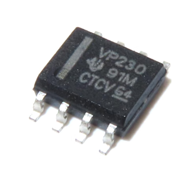
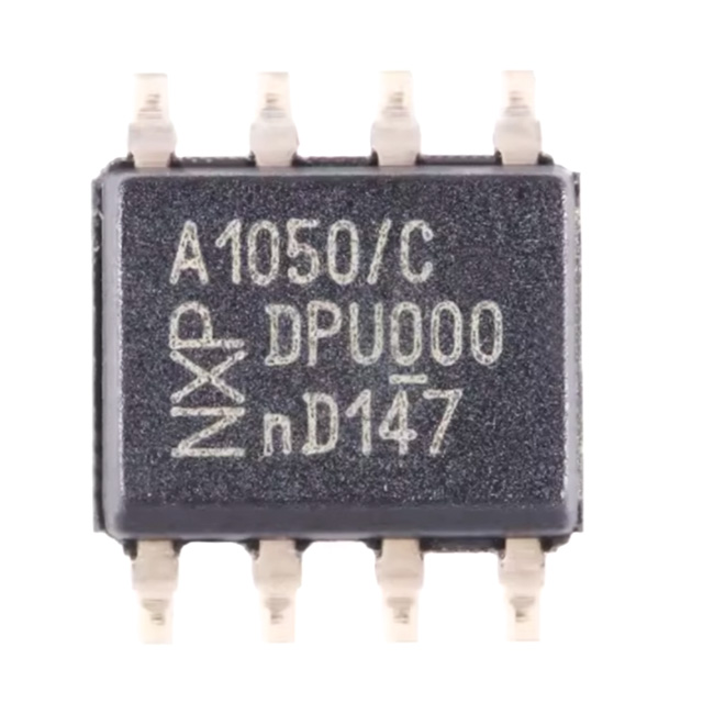
Sn65hvd230d Equivalent Can Transceiver

| Parameters |
SN65HVD230D |
TJA1050 |
MCP2551 |
| पैकेज का प्रकार |
एसओआईसी-8 |
SOIC-8, DIP-8 |
SOIC-8, DIP-8 |
| Operating Voltage Range |
4.5 वी ~ 5.5 वी |
4.5 वी ~ 5.5 वी |
4.5 वी ~ 5.5 वी |
| Max Data Transfer Rate |
1 Mbps |
1 Mbps |
1 Mbps |
| Temperature Range |
-40°C ~ +125°C |
-40°C ~ +125°C |
-40°C ~ +125°C |
| Total Protection |
Internal short circuit and thermal shutdown protection |
Internal short circuit and thermal shutdown protection |
Internal short circuit and thermal shutdown protection |
| Quiescent Current |
10 µA (standby mode) |
10 µA (standby mode) |
10 µA (standby mode) |
| Transmission Mode |
CAN 2.0A/B, 1 Mbps |
CAN 2.0A/B, 1 Mbps |
CAN 2.0A/B, 1 Mbps |
| ESD Protection |
±8 kV (direct contact) |
±8 kV (direct contact) |
±8 kV (direct contact) |
| End-of-Line Support |
नहीं |
नहीं |
नहीं |
When choosing a replacement for the SN65HVD230D, make sure the model you select comes in a compatible package like एसओआईसी-8 या डीआईपी-8, which is standard across options like the TJA1050, MCP2551. These models all operate within the 4.5V to 5.5V voltage range and support a 1 Mbps data rate, which is typical for most CAN bus applications. While they offer low standby current for power efficiency, you should check the specific power requirements, especially for battery-powered setups. They also have a broad operating temperature range of -40°C to +125°C and provide ±8kV ESD protection, with only MCP2551 supporting termination resistors.
Sn65hvd230d Can Bus Circuit Example

This circuit lets your microcontroller, like an ESP32, communicate smoothly with a CAN bus network using the SN65HVD230D transceiver. Here’s how it works: when your ESP32 sends data through the ESP_CAN_TX pin, the SN65HVD230D chip converts these digital signals into differential signals (CANH and CANL) and sends them out onto the CAN bus lines. Incoming CAN signals from the network are converted back into digital signals and sent to your microcontroller via the ESP_CAN_RX pin.
You control its operation mode using the CAN_STBY pin: pulling it low (GND) enables high-speed communication; pulling it high (VCC) puts it into low-power standby mode.
For reliable communication, the circuit includes protections like a common-mode choke for EMI suppression, PTC fuses to protect from short circuits, ESD diodes to guard against static, and capacitors for noise filtering. Don’t forget to add 120Ω termination resistors at each bus end and use a stable 3.3V power supply.
Sn65hvd230d Arduino Can Bus Wiring
The SN65HVD230D is a handy CAN-bus transceiver chip that lets your Arduino (or other MCU) communicate reliably over a CAN network. It takes digital signals from your Arduino and converts them into differential signals (CANH and CANL) suitable for CAN lines. Likewise, it converts incoming CAN signals back into digital signals for your Arduino.
Here’s how you connect it: your Arduino communicates via an SPI interface (MOSI, MISO, SCK, CS) to a CAN controller like the MCP2515. The CAN controller then connects its TXD and RXD pins to the SN65HVD230D’s D (transmit) and R (receive) pins. Connect VCC (usually 3.3V) and ground properly, and link CANH and CANL to the bus lines. Add a 120Ω resistor at each bus end to prevent signal reflections. Also, use twisted-pair cables for better noise resistance. For simplicity, you might choose a ready-made MCP2515+SN65HVD230D module—perfect for
Sn65hvd230d 3.3v Logic Compatibility
The SN65HVD230D is a CAN-bus transceiver specifically designed for easy connection with 3.3V logic-level MCUs like the ESP32, STM32, or Raspberry Pi RP2040. It operates smoothly between 3.0V and 3.6V, meaning you can directly connect it to your microcontroller’s GPIO pins without any extra level converters.
Because it’s optimized for 3.3V logic, it saves power, making it perfect if you’re building battery-powered or IoT devices. Connect your MCU’s TX pin directly to the chip’s D input, and RX pin to its R output. Don’t mix it with 5V logic—stick strictly to 3.3V to avoid damaging it.
Always use a stable 3.3V power supply and add a 0.1μF decoupling capacitor to ensure reliable communication. For the CAN bus itself, use twisted-pair wiring and add 120Ω termination resistors at each end to maintain signal quality.
Sn65hvd230d Automotive Can Interface
The SN65HVD230D is a CAN transceiver designed for automotive systems, ensuring reliable data transmission in harsh environments. It works well in engine control units (ECU), body control systems, safety systems (like airbags), and entertainment systems. This chip supports CAN 2.0A/B protocols and operates in noisy conditions, ensuring stable communication.
It runs on a 4.5V to 5.5V voltage range and has a wide temperature range from -40°C to +125°C, making it perfect for the automotive industry. The chip’s differential signal transmission helps reduce noise and interference, while its built-in short circuit and thermal shutdown protection ensure the system stays safe.
In applications like ECU communication, infotainment systems, and autonomous driving, the SN65HVD230D provides reliable, high-speed communication. For long-distance and high-reliability communication, always use 120Ω termination resistors at both ends of the CAN bus.
Sn65hvd230d Esp32 Integration
Here’s how ESP32 communicates with the CAN bus using the SN65HVD230D और MCP2515:
First, the ESP32 communicates with the MCP2515 through the SPI interface (SCK, MOSI, MISO, and CS). The MCP2515 handles the CAN protocol and converts the digital signals from the ESP32 into CAN frames.
Then, the MCP2515 sends data to the SN65HVD230D via its टीएक्सडी pin, which converts it into differential signals (CANH and CANL) for transmission on the CAN bus.
When receiving data, the SN65HVD230D converts the differential signals back into digital signals, sending them to the MCP2515, which then passes the data back to the ESP32.
For reliable communication, 120Ω termination resistors should be placed at both ends of the CAN bus to prevent signal reflection. The RS pin on the SN65HVD230D controls its mode: जीएनडी for normal operation and वीसीसी for low-power standby.
Sn65hvd230d Termination Resistor Value
When using the SN65HVD230D in your CAN bus setup, it’s important to use termination resistors to ensure reliable communication, especially in longer networks or when multiple devices are involved.
The recommended termination resistor value is 120Ω, and you’ll need to place it at both ends of the CAN bus, between the CAN_H और CAN_L lines. This resistor helps to prevent signal reflection, keeping the data clear and ensuring smooth communication.
Make sure to only add termination resistors at the two ends of the bus—no termination in the middle. For high-speed networks (like 1 Mbps), these resistors are essential to maintain signal integrity.
In short, use a 120Ω resistor at each end of your CAN bus to keep your signals clean and communication stable.
Sn65hvd230d Isolated Can Design
To design an isolated CAN bus with the SN65HVD230D, you’ll need to ensure electrical isolation between your microcontroller (MCU) and the CAN transceiver to protect sensitive components from voltage spikes and interference.
First, use a CAN bus isolator like the ISO1050 या ADM3053 between the MCU and the SN65HVD230D. This isolator will separate the logic side from the physical CAN layer, protecting both sides from each other’s electrical noise.
For complete isolation, use a DC-DC converter to provide isolated power to the SN65HVD230D, keeping the grounds of the MCU and CAN transceiver separate.
Also, place 120Ω termination resistors at both ends of the CAN bus to prevent signal reflections and ensure clean communication. For better signal integrity, consider adding filter capacitors near the transceiver and isolators.
This setup improves noise immunity, safety, and protection against ground loops, making it ideal for industrial and automotive applications.


