TM4C123GH6PMI datasheet & Tiva C series | pdf
- ब्रांड: टेक्सास इंस्ट्रूमेंट्स
- डाउनलोड करना: TM4C123GH6PMI Datasheet PDF
- कीमत: जाँच करना
- स्टॉक में: 14,088
- कोरप्रोसेसर: ARM® Cortex®-M4F
- कोर आकार: 32-बिट सिंगल-कोर
- बाह्य उपकरण: Brown-out Detect/Reset, DMA, Motion PWM, POR, WDT
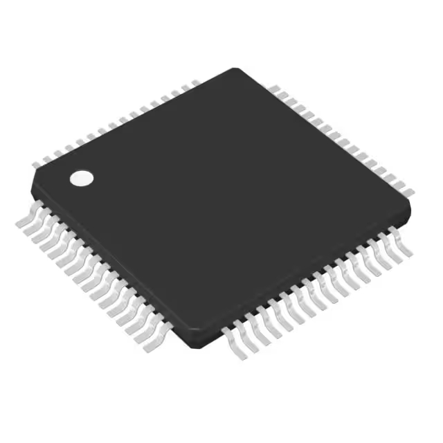
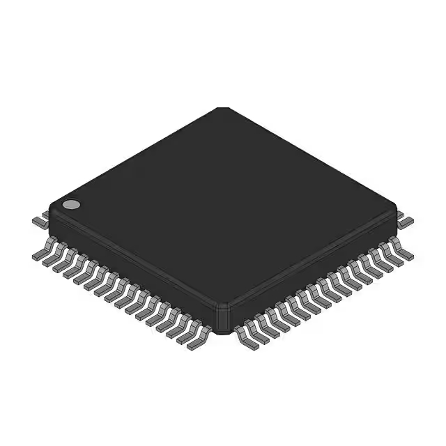
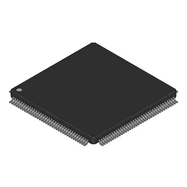
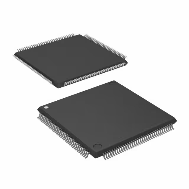
- पैकेट: 64-एलक्यूएफपी

HK$250.00 से अधिक ऑर्डर पर निःशुल्क डिलीवरी

त्वरित प्रतिक्रिया, त्वरित उद्धरण

फ्लैश शिपमेंट, बिक्री के बाद कोई चिंता नहीं

मूल चैनल, प्रामाणिक उत्पादों की गारंटी
tm4c123gh6pmi
The TM4C123GH6PMI is a powerful microcontroller with plenty of features. It’s powered by an ARM Cortex-M4 core, with a floating-point unit for fast calculations, running at a max speed of 80 MHz. You get 512 KB of flash memory for storing code, 128 KB of SRAM for data, and 4 KB of EEPROM for non-volatile storage.
It also has a range of peripherals, including timers, PWM outputs for controlling motors and lights, a 12-bit ADC for sensor readings, and a 12-bit DAC for converting digital to analog signals. Communication is covered with multiple UARTs, I2C, and SPI ports, plus a USB 2.0 controller for data transfer.
This microcontroller supports low-power modes, operates at 3.3V, and offers 10/100 Ethernet and CAN support. It’s ideal for a range of applications, from networking to automotive. Plus, you can easily develop software for it with popular tools like Code Composer Studio and Keil MDK.
tm4c123gh6pmi pinout diagram
| पिन नंबर | पिन नाम | समारोह |
|---|---|---|
| 1 | वीडीडी | Power supply (3.3V) |
| 2 | VSS | मैदान |
| 3 | एनसी | No connection |
| 4 | JTAG TDI | JTAG Test Data Input |
| 5 | JTAG TDO | JTAG Test Data Output |
| 6 | JTAG TMS | JTAG Test Mode Select |
| 7 | JTAG TCK | JTAG Test Clock |
| 8 | PWM0 | PWM Output 0 |
| 9 | PWM1 | PWM Output 1 |
| 10 | PWM2 | PWM Output 2 |
| 11 | GPIOA0 | General Purpose I/O Pin |
| 12 | GPIOA1 | General Purpose I/O Pin |
| 13 | GPIOA2 | General Purpose I/O Pin |
| 14 | GPIOA3 | General Purpose I/O Pin |
| 15 | UART0 RX | UART0 Receive |
| 16 | UART0 TX | UART0 Transmit |
| 17 | I2C0 SDA | I2C0 Data |
| 18 | I2C0 SCL | I2C0 Clock |
| 19 | SPI0 MOSI | SPI0 Master Out Slave In |
| 20 | SPI0 MISO | SPI0 Master In Slave Out |
| 21 | SPI0 SCK | SPI0 Clock |
| 22 | ADC0 CH0 | ADC0 Channel 0 |
| 23 | ADC0 CH1 | ADC0 Channel 1 |
| 24 | ADC0 CH2 | ADC0 Channel 2 |
| 25 | ADC0 CH3 | ADC0 Channel 3 |
| 26 | TIMER0 | Timer 0 Input Capture |
| 27 | TIMER1 | Timer 1 Input Capture |
| 28 | TIMER2 | Timer 2 Input Capture |
| 29 | CAN0 TX | CAN0 Transmit |
| 30 | CAN0 RX | CAN0 Receive |
| 31 | USB0 DP | USB Data Plus |
| 32 | USB0 DM | USB Data Minus |
| 33 | ETH0 TXD0 | Ethernet Transmit Data 0 |
| 34 | ETH0 TXD1 | Ethernet Transmit Data 1 |
| 35 | ETH0 RXD0 | Ethernet Receive Data 0 |
| 36 | ETH0 RXD1 | Ethernet Receive Data 1 |
| 37 | GPIOB0 | General Purpose I/O Pin |
| 38 | GPIOB1 | General Purpose I/O Pin |
| 39 | GPIOB2 | General Purpose I/O Pin |
| 40 | GPIOB3 | General Purpose I/O Pin |
| 41 | GPIOC0 | General Purpose I/O Pin |
| 42 | GPIOC1 | General Purpose I/O Pin |
| 43 | GPIOC2 | General Purpose I/O Pin |
| 44 | GPIOC3 | General Purpose I/O Pin |
| 45 | PWM3 | PWM Output 3 |
| 46 | PWM4 | PWM Output 4 |
| 47 | TIMER3 | Timer 3 Input Capture |
| 48 | TIMER4 | Timer 4 Input Capture |
| 49 | TIMER5 | Timer 5 Input Capture |
| 50 | VSS | मैदान |
| 51 | वीडीडी | बिजली की आपूर्ति |
| 52 | VSS | मैदान |
| 53 | वीडीडी | बिजली की आपूर्ति |
| 54 | IO0 | General Purpose I/O Pin |
| 55 | IO1 | General Purpose I/O Pin |
| 56 | IO2 | General Purpose I/O Pin |
| 57 | IO3 | General Purpose I/O Pin |
| 58 | RESET | Reset Pin |
| 59 | NRST | Reset Pin |
| 60 | XIN | External Oscillator Input |
| 61 | XOUT | External Oscillator Output |
| 62 | VREF | Voltage Reference |
| 63 | DIO | Digital I/O Pin |
| 64 | CLKOUT | Clock Output |
When wiring up the microcontroller, here are a few key things to keep in mind:
For power, connect वीडीडी to your 3.3V power supply and VSS to ground—this is crucial for the chip to work properly. The microcontroller also supports several communication protocols: UART (pins 15 and 16) for serial communication, आई2सी (pins 17 and 18) for peripheral communication, and एसपीआई (pins 19-21) for high-speed data transfer. If you’re working with automotive or industrial networks, use the कर सकना pins (29 and 30).
There are GPIO pins for general input/output that can be configured for tasks like reading sensors or driving outputs, and some of these pins have alternate functions like PWM or ADC. For timing and analog-to-digital conversions, you’ll need to use the timer और एडीसी pins (22-25, 26-28). The RESET pin is for restarting the microcontroller if needed.
Make sure everything is connected to a stable 3.3V power source, and if you need precise timing, don’t forget to connect the XIN और XOUT pins for an external crystal oscillator.
tm4c123gh6pmi equivalent microcontroller
| विशेषता | TM4C123GH6PMI | STM32F103RBT6 | MKL25Z128VLK4 |
|---|---|---|---|
| Core | ARM Cortex-M4 with FPU | ARM Cortex-M3 | ARM Cortex-M0+ |
| Clock Speed | 80 मेगाहर्ट्ज | 72 MHz | 48 MHz |
| Flash Memory | 512 KB | 128 KB | 128 KB |
| SRAM | 128 KB | 20 KB | 16 KB |
| ईईपीरोम | 4 KB | No EEPROM | No EEPROM |
| GPIO Pins | 43 | 37 | 34 |
| PWM Outputs | 6 | 6 | 4 |
| ADC Channels | 16 | 16 | 12 |
| एसपीआई | 6 | 2 | 2 |
| आई2सी | 4 | 2 | 2 |
| UART | 8 | 4 | 4 |
| कर सकना | 1 | No CAN | No CAN |
| USB | Full-Speed USB 2.0 | No USB | No USB |
| ईथरनेट | 10/100 Ethernet | No Ethernet | No Ethernet |
| Power Supply | 3.3 | 3.3 | 3.3 |
| पैकेट | 64-pin LQFP | 64-pin LQFP | 64-pin LQFP |
The TM4C123GH6PMI is a powerful microcontroller with a Cortex-M4 core running at 80 MHz, making it great for complex tasks and high-speed operations. It also offers a lot of memory—512 KB flash and 128 KB SRAM—along with plenty of peripherals like 8 UARTs, 6 SPI, and USB/Ethernet support.
The STM32F103RBT6, with its Cortex-M3 core at 72 MHz, is slightly slower but still good for many applications. It has 128 KB of flash memory and fewer peripherals, lacking USB and Ethernet support.
The MKL25Z128VLK4, using a Cortex-M0+ core at 48 MHz, is more power-efficient but less powerful. It’s suitable for simple, low-power applications but lacks the advanced peripherals like USB or Ethernet.
So, if you need power and connectivity, the TM4C123GH6PMI is the best choice. The STM32F103RBT6 works well for moderate tasks, while the MKL25Z128VLK4 is perfect for simpler, low-power systems.
tm4c123gh6pmi development board wiring

The TM4C123GH6PMI microcontroller on this development board is the heart of your project. It’s located in the center of the board in a 64-pin LQFP package. All your external components like LEDs, sensors, and motors connect through the GPIO pins, communication interfaces (UART, SPI, I2C), PWM pins, and ADC channels.
For programming and debugging, the mikroProg interface connects to the SWD or JTAG pins, with the USB port making it easy to load your code and troubleshoot.
The board gets power from either a DC input (7-12V) or micro USB (5V or 3.3V). The onboard regulator ensures everything gets the right voltage.
The board offers lots of flexibility with access to GPIO pins from PORTA to PORTJ, plus PWM outputs for motor control. It also supports communication interfaces like UART, SPI, and I2C, and even Ethernet or USB for networking.
tm4c123gh6pmi tm4 launchpad circuit example

The TM4C123GH6PMI microcontroller is the main processor here, working with the LSM12H12TR sensor and other peripherals. The reset pin (RST) is connected to an external reset mechanism, like a button, to restart the system when needed. The LSM12H12TR sensor, likely a motion sensor, communicates through एसपीआई और आई2सी interfaces. The SCL/SCK, SDA/SDI, and सी pins manage the clock, data, and chip select for communication.
The microcontroller is powered by 3.3, and a current-limiting resistor (R1) protects the circuit from excessive current, especially for the LED (LD1). Interrupts (INT1 and INT2) handle changes in input or sensor signals, and buttons let you select communication settings. The C3 capacitor stabilizes power to sensitive components. Finally, the PWR LED shows the system’s power status.
Make sure everything is wired correctly for smooth operation, especially power and communication settings.
tm4c123gh6pmi uart spi i2c setup
To set up communication interfaces on the TM4C123GH6PMI, here’s a quick guide:
For UART, you first enable UART and GPIO ports, configure the TX and RX pins, then set the baud rate and other parameters like data bits. Once done, you can send and receive data via the UART registers.
For एसपीआई, enable the SPI and GPIO ports, configure the pins for MOSI, MISO, SCK, and SS, and set the SPI parameters like clock polarity and baud rate. You can then use the SPI registers to send and receive data.
For आई2सी, enable the I2C and GPIO ports, then set up the SCL and SDA pins. Configure I2C settings like the clock speed and master/slave mode. After that, you can use the I2C registers to send and receive data.
Make sure to connect the peripherals to the correct pins and configure the microcontroller for the protocol you’re using.
tm4c123gh6pmi pwm motor control tutorial
PWM (Pulse Width Modulation) lets you control a motor’s speed by adjusting how much time the signal stays high during each cycle. With the TM4C123GH6PMI, you can generate a PWM signal and use it to control the motor through a motor driver like an H-Bridge.
To set it up, start by enabling the clock for PWM and GPIO peripherals. Choose the correct PWM pins (like PA6 for PWM0), and configure them for output. Set the PWM frequency (for example, 1 kHz) to adjust the motor’s speed, and then set the duty cycle—the higher the duty cycle, the faster the motor.
Once the PWM signal is generated, connect it to the motor driver. If using an H-Bridge, you can also control the motor’s direction. By adjusting the duty cycle, you can easily change the motor’s speed.







.jpg)


