This schematic shows a simple and effective power design for the AD9361BBCZ SDR transceiver. It uses the ADP5040 PMIC to provide clean 1.8V and 3.3V rails, and an additional ultra-stable 1.3V through the ADP1755 regulator for the chip’s core digital and analog circuits. Perfect if you’re building embedded SDR modules, small base stations, or MIMO systems—clean and stable power is key for top RF performance.

AD9361BBCZ データシートと価格
Explore the AD9361BBCZ Reference Manual for comprehensive details and specifications. Find all the essential information, including pricing, to help you utilize this component effectively in your projects.
- タイプ: 処方箋のみ
- RFファミリー/標準: セルラー
- プロトコル: LTE
- パッケージ: 144-LFBGA、CSPBGA


HK$250.00以上のご注文で送料無料

迅速な対応、迅速な見積もり

すぐに発送、アフターサービスも安心

オリジナルチャネル、本物の製品の保証
AD9361BBCZ DataSheet — ingketech.net
AD9361BBCZ
If you’re working on SDR or wireless communication projects, the AD9361BBCZ transceiver is an ideal choice. It covers a wide frequency range (70 MHz to 6 GHz), handling LTE, WiFi, 5G and more. Bandwidth is adjustable (200 kHz–56 MHz), and it integrates mixers, filters, ADCs, and DACs, simplifying your RF design. With support for 2×2 MIMO, high performance, and low power consumption, it’s perfect for portable devices, small base stations, wireless video, radar, and similar applications.
AD9361BBCZ Pinout Diagram
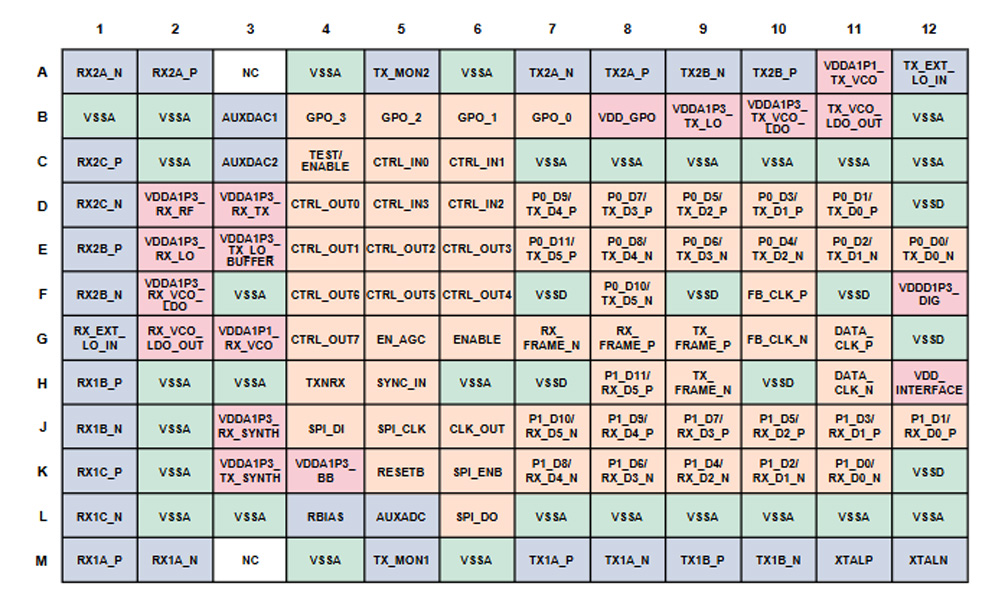
| Pin Type | Typical Pins | 機能説明 |
|---|---|---|
| Power Supply Pins | VDD_GPO, VDDD (1.3V), VDD_INTERFACE (1.2V–2.5V) | Provide independent power domains for different modules; analog paths and digital I/O powered separately |
| Ground Pins | VSSA (analog ground), VSSD (digital ground) | Separate analog and digital grounds; strict PCB ground plane separation required |
| RF Input/Output Pins | TX2A_P/N, TX2B_P/N, RX2C_P/N, etc. | High-frequency analog transmit/receive paths, supports differential RF signal communication |
| Control Signal Pins | CTRL_IN03, CTRL_OUT07, EN_AGC | Manual gain control, AGC enable, status monitoring, etc. |
| Digital Interface Pins | P0_Dx, P1_Dx, DATA_CLK_P/N | CMOS/LVDS interface, used for data exchange with FPGA or microcontrollers |
| Reset & SPI Pins | RESETB, SPI_ENB | Reset chip and enable SPI interface, used for external configuration control |
When designing with the AD9361BBCZ, separate analog, digital, and IO power rails clearly with proper decoupling. For grounding, route analog and digital grounds separately and join near the chip to reduce interference. RF pins (TX/RX) require accurate 50Ω matching; unused pins can connect to a 1.3V bias voltage. Digital interfaces (CMOS or LVDS) need SPI configuration first. Follow the official reference layout with Rogers PCB materials and impedance control for best RF performance.
AD9361BBCZ Equivalent RF Transceiver
| パラメータ/モデル | AD9361BBCZ | AD9364BCPZ | ADRV9002 |
|---|---|---|---|
| パッケージ | 144-BGA (10×10 mm) | 144-BGA (10×10 mm) | 15×15 mm multi-BGA |
| RF Coverage Range | 70 MHz – 6.0 GHz | 70 MHz – 6.0 GHz | 30 MHz – 6.0 GHz |
| Channel Configuration | 2×Tx / 2×Rx MIMO | 1×Tx / 1×Rx | 2×Tx / 2×Rx + 2×Rx monitor |
| Channel Bandwidth | 200 kHz – 56 MHz | 200 kHz – 56 MHz | Wider (high-performance ADC/DAC) |
| Noise Figure (NF) | < 2.5 dB | < 2.5 dB | Optimized, high sensitivity (~3 dB) |
| ADC / DAC Resolution | 12-bit, 2 channels each | 12-bit, 1 channel each | 16-bit, high resolution |
| Auto Calibration | サポートされている | サポートされている | Supported, more advanced |
| 消費電力 | ~600–700 mW (full load) | Similar | ~1W/channel, higher consumption |
| Target Applications | SDR, base station, wireless test systems | Cost-sensitive, single-channel systems | Defense, 5G, electronic warfare, high-end systems |
If you can’t get the AD9361, consider the AD9364 or ADRV9002. The AD9364 is almost identical but supports single-channel only—no MIMO. It’s cheaper if you don’t need dual channels. For better performance, higher accuracy, and lower distortion, choose ADRV9002, but remember it consumes more power and requires different interfaces and power management. Pay attention to RF layout, impedance matching, and interface changes when switching.
AD9361BBCZ SDR Transceiver Circuit Example

AD9361BBCZ Linux Driver Setup
AD9361BBCZ High Frequency Radio Board
If you’re building an advanced wireless radio board for SDR, 5G, or radar applications, the AD9361BBCZ is perfect. Covering frequencies from 70 MHz to 6 GHz, it handles narrowband and wideband signals with ease. It also supports dual-channel MIMO, great for antenna arrays. Pair it with suitable power management (ADP5040+ADP1755), clock references, and RF matching networks, then connect to an FPGA using SPI/LVDS. ADI’s Linux drivers and tools like libiio make development straightforward.
同様のもの

N000900L006A
Cambium
NB-N500032A-GL
Cambium
N000000T001A
Cambium
85009325001
Cambium
N110082L141A
Cambium
N110082L145A
Cambium
C030045C001A
Cambium
C060082R084A
Cambium
C800082K003A
Cambium
MT-650-63
CommScope
C024045C002A
Cambium
N110082L131A
Cambium
カートに追加する
AM424-435D1110
Anatech Electronics Inc.
GLP-ENC-EXT420-001-DP
Synapse Wireless
LPLM-010-13303.4-0-15P-06401
L3 Narda-MITEQ
DG-EXT-200-UR-B
Digi

AD9863BCP-50
アナログ・デバイセズ株式会社

DS-117-PIN
MACOMテクノロジーソリューションズ

D4I3570
DiTom Microwave
TLH5016HN/V1WY
NXP USA Inc.
2663.000.00.00
フェイグ・エレクトロニック

QMC-WC12-1FR
Quantum Microwave Components
SI2182-A50-GM
スカイワークスソリューションズ株式会社
V600-A44 5M
オムロンオートメーション&セーフティ
関連製品
N000900L006A
Cambium
NB-N500032A-GL
Cambium
N000000T001A
Cambium
85009325001
Cambium
N110082L141A
Cambium
N110082L145A
Cambium
C030045C001A
Cambium
C060082R084A
Cambium
C800082K003A
Cambium
MT-650-63
CommScope
C024045C002A
Cambium
N110082L131A
Cambium
N110082L132A
Cambium
IP-20C_DC_CONN
Ceragon
N060082L136A
Cambium
C110082B056A
Cambium
N000065L001C
Cambium
DA-C200
CommScope
N110082L180A
Cambium
N000000T002A
Cambium

ANK-910M
Com-Power Corporation
ANK-910L
Com-Power Corporation
ANK-318
Com-Power Corporation
ANK-140
Com-Power Corporation
APF-5060
Com-Power Corporation
AMTTC-300
Com-Power Corporation
AT-812
Com-Power Corporation
ANK-310
Com-Power Corporation
AM-400A
Com-Power Corporation
AT-220
Com-Power Corporation
RFQ をお送りください。すぐに対応させていただきます。

RFQ をお送りください。すぐに対応させていただきます。
著作権 © 2024 無断複写・転載を禁じます