HK$250.00以上のご注文で送料無料

迅速な対応、迅速な見積もり

すぐに発送、アフターサービスも安心

オリジナルチャネル、本物の製品の保証
Key Features of the ASM1061 SATA III to PCIe Bridge
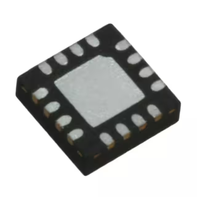
その ASM1061 is a reliable and efficient SATA III to PCIe bridge chip that enables high-speed data transfer between SATA devices and PCIe-based systems. It supports SATA III (6Gbps) and PCIe 2.0, making it ideal for applications like storage expansions, add-in cards, or connecting SSDs to PCIe slots. With its low power consumption and compact design, the ASM1061 ensures smooth and fast data handling while minimizing energy usage. It also supports hot-plugging, making it convenient for users to connect and disconnect devices without powering down the system. Whether you’re looking to expand storage or add SATA devices to your PCIe-enabled system, the ASM1061 offers a solid solution.
ASM1061 Pinout
| ピン | Label | 説明 |
|---|---|---|
| 1 | GND | Ground pin, connected to the common ground of the circuit. |
| 2 | VDD | Power supply pin, typically 3.3V for the chip. |
| 3 | PCIe_TX+ | PCIe transmit positive signal for data transfer. |
| 4 | PCIe_TX- | PCIe transmit negative signal for data transfer. |
| 5 | PCIe_RX+ | PCIe receive positive signal for data reception. |
| 6 | PCIe_RX- | PCIe receive negative signal for data reception. |
| 7 | SATA_TX+ | SATA transmit positive signal for data transfer. |
| 8 | SATA_TX- | SATA transmit negative signal for data transfer. |
| 9 | SATA_RX+ | SATA receive positive signal for data reception. |
| 10 | SATA_RX- | SATA receive negative signal for data reception. |
| 11 | 導かれた | LED indicator pin to show the status of the data connection. |
Using the ASM1061 Pinout
その ASM1061 is designed to connect a SATA device to a PCIe bus. The PCIe_TX+ そして PCIe_TX- pins (Pins 3 and 4) handle outgoing data transmission, while PCIe_RX+ そして PCIe_RX- (Pins 5 and 6) are responsible for receiving data. Similarly, the SATA_TX+ そして SATA_TX- pins (Pins 7 and 8) transmit data to the SATA device, while SATA_RX+ そして SATA_RX- (Pins 9 and 10) receive data from the device. Ensure that the power supply (VDD) is connected properly to avoid malfunction, and the 導かれた pin (Pin 11) is used to indicate the device’s operational status. Proper grounding and voltage levels are essential for optimal performance and preventing damage to the chip.
ASM1061 Equivalent Models
Here’s a comparison of equivalent SATA to PCIe bridge chips with similar packaging and features:
| モデル | SATA Version | PCIe Version | Maximum Data Rate | パッケージタイプ | 主な特徴 |
|---|---|---|---|---|---|
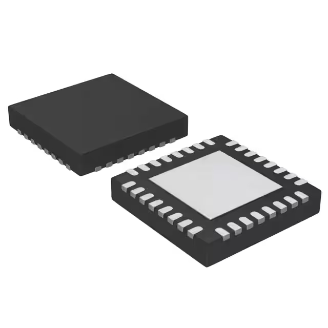
| ASM1061 | SATA III (6Gbps) | PCIe 2.0 | 6Gbps | QFN-32 | Low power, hot-plug support, small form factor |
| ASM1062 | SATA III (6Gbps) | PCIe 2.0 | 6Gbps | QFN-32 | Improved signal integrity, hot-plug support |
| JMB585 | SATA III (6Gbps) | PCIe 3.0 | 8Gbps | QFN-28 | Faster PCIe 3.0 support, lower latency |
| Marvell 88SE9215 | SATA III (6Gbps) | PCIe 2.0 | 6Gbps | QFN-32 | Enhanced compatibility with RAID and storage systems |
Substitution Tips
When replacing the ASM1061, make sure the SATA version そして PCIe version are compatible with your system. For example, the ASM1062 is a close alternative with similar features and is often used for similar low-power, hot-plug applications. If you need a faster PCIe connection, the JMB585 supports PCIe 3.0, providing higher throughput, but make sure your system supports PCIe 3.0. For more advanced RAID or storage system compatibility, consider the Marvell 88SE9215, which also supports RAID features but in a smaller package. Always verify the data rate そして package type to ensure they fit your design requirements.
ASM1061 Firmware
その ASM1061 firmware plays a key role in managing the communication between the SATA devices and the PCIe bus. This firmware ensures that data is transferred efficiently by controlling the data flow and enabling features like hot-plugging. It’s crucial to ensure that the firmware is up to date to avoid compatibility issues with newer storage devices and ensure smooth operation. Firmware updates can be provided by the manufacturer, improving performance and adding new features to the chip.
ASM1061 SATA Controller
その ASM1061 SATA controller is a highly efficient bridge that converts the SATA interface to PCIe, allowing devices like SSDs and hard drives to connect to a PCIe slot. It supports SATA III (6Gbps), ensuring fast data transfer speeds for modern storage solutions. The controller provides reliable performance for applications such as data storage, RAID configurations, and expansion cards. With its compact design and low power consumption, the ASM1061 is a great choice for integrating SATA devices into PCIe systems.
Here’s a practical overview of the ASM1061 SATA to PCIe bridge circuit, focusing on its key components and how they work together:
ASM1061 Circuit Overview
その ASM1061 is a PCIe Gen2 to SATA III (6Gbps) bridge controller. It enables the connection of SATA devices (like SSDs or HDDs) to a PCIe slot, commonly used in desktop PCs or expansion cards.
Key Components:
-
PCIe Interface: Handles data transfer between the motherboard and the ASM1061 chip.
-
SATA Ports: Two SATA III ports (Port A and Port B) for connecting storage devices.
-
電源: Requires 3.3V and 1.25V power rails for operation.
-
Crystal Oscillator: A 20MHz external crystal is used for clock generation.
-
GPIOピン: General-purpose input/output pins for additional functionalities.
-
LED Indicator: Indicates the activity status of the connected SATA devices.
Typical Circuit Features:
-
Power Regulation: An integrated 3.3V to 1.25V switch regulator ensures stable power supply to the chip.
-
Signal Integrity: Differential signaling is used for both PCIe and SATA interfaces to maintain data integrity over high-speed connections.
-
Hot-Plug Support: The design supports hot-plugging of SATA devices, allowing for device addition or removal without shutting down the system.
Considerations:
-
Component Placement: Proper placement of decoupling capacitors near power pins is crucial to minimize noise and ensure stable operation.
-
熱管理: Adequate heat sinking may be necessary, especially in high-performance applications, to prevent overheating.
-
Signal Routing: Careful PCB layout is required to maintain signal integrity, particularly for high-speed differential pairs.
For a detailed schematic and further information, you can refer to the official datasheet:




,SOT157-2.JPG)
,SOT523-1.JPG)

