
ATTINY85-20PU データシート、価格、ピン配置、PDF
- コアプロセッサ: AVR
- コアサイズ: 8ビット
- 周辺機器: ブラウンアウト検出/リセット、POR、PWM、WDT
- パッケージ: 8-DIP(0.300、7.62mm)


HK$250.00以上のご注文で送料無料

迅速な対応、迅速な見積もり

すぐに発送、アフターサービスも安心

オリジナルチャネル、本物の製品の保証
How to program Digispark ATtiny85 | Updated working method 2025
ATTINY85-20PU
The ATtiny85-20PU from Atmel (now Microchip) is a neat little 8-bit AVR microcontroller, perfect if you’re tight on space or power. It’s great for building mini USB gadgets, simple sensors, or compact controllers.
It runs smoothly on an AVR-based RISC architecture at up to 20 MHz—just right for most simple projects. You get 8KB of flash memory, enough to handle basic control logic, along with 512 bytes each of SRAM and EEPROM for temporary or persistent storage.
There are up to 6 I/O pins, some capable of ADC, PWM, SPI, and I²C (via USI). It operates comfortably from 2.7V to 5.5V, perfect for common power setups, and the low-power sleep modes make it ideal for battery-powered devices. Plus, the DIP-8 package makes it easy for you to plug into breadboards or solder by hand—perfect for DIY electronics.
ATTINY85-20PU Pinout and Functions
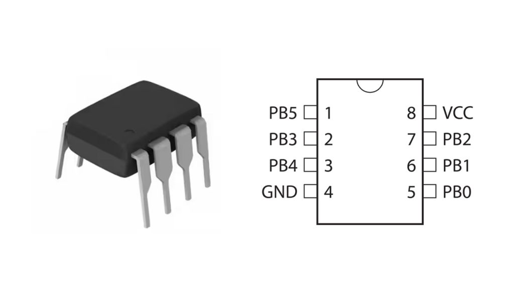
| ピン | 名前 | Function(s) |
|---|---|---|
| 1 | PB5 | (RESET) / ADC0 / dW (debugWire) |
| 2 | PB3 | Digital I/O / PWM / ADC3 / SPI MISO |
| 3 | PB4 | Digital I/O / PWM / ADC2 / SPI SCK |
| 4 | GND | 地面 |
| 5 | PB0 | Digital I/O / PWM / ADC0 / AREF / SPI MOSI |
| 6 | PB1 | Digital I/O / PWM / ADC1 |
| 7 | PB2 | Digital I/O / INT0 / ADC1 / USI SDA (I²C) |
| 8 | VCC | Power Supply (2.7V–5.5V) |
When you’re working with the ATtiny85, keep a few tips in mind. Pin 1 (PB5) is set as RESET by default. If you want it as a regular IO pin, you’ll have to change the fuse settings, but then you won’t be able to use ISP programming afterward.
Each pin has multiple functions—ADC, PWM, SPI, I²C (via USI)—but you can’t use them all simultaneously. Stick to a stable 5V or 3.3V power supply, as anything higher might fry the chip.
Even though it’s tiny (just 8 pins), it offers plenty of resources. It’s perfect for ultra-compact projects like Digispark boards, mini USB gadgets, LED controllers, or lightweight sensor setups. Plus, if you prefer the Arduino environment, there’s specific core support available to make things easier.
ATTINY85-20PU Equivalent Microcontroller
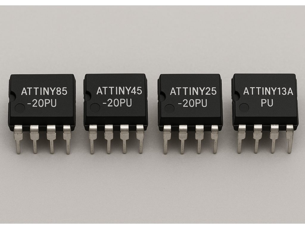
| パラメータ | ATTINY85-20PU | ATTINY45-20PU | ATTINY25-20PU | ATTINY13A-PU |
|---|---|---|---|---|
| フラッシュ | 8KB | 4KB | 2KB | 1KB |
| SRAM | 512B | 256B | 128B | 64B |
| EEPROM | 512B | 256B | 128B | 64B |
| Max Clock Speed | 20MHz | 20MHz | 20MHz | 20MHz |
| 動作電圧 | 2.7–5.5V | 2.7–5.5V | 2.7–5.5V | 1.8–5.5V |
| I/Oピン | 6 | 6 | 6 | 6 |
| ADCチャンネル | 4 | 4 | 4 | 4 |
| Architecture Compatibility | Fully Compatible | Fully Compatible | Fully Compatible | Compatible with fewer resources |
If you’re looking to replace an ATtiny85-20PU, you could go with ATTINY45-20PU or ATTINY25-20PU. They’re basically identical but have less memory, making them ideal if your project’s small and doesn’t need much storage. ATTINY13A-PU shares the same pin layout, but it’s really limited resource-wise—perfect for simple tasks like blinking an LED or basic switches, but no good for complex projects.
Two other DIP-8 chips often pop up but are totally different:
The PIC12F675 uses a completely different architecture (Microchip PIC), so you’d need different programming tools and environment. You can’t reuse your ATtiny code directly.
ATTINY85-20PU Programming Circuit

This circuit lets you use an Arduino Nano as a programmer to upload code onto your ATTiny85-20PU chip.
Here’s how it works: Your Nano supplies 5V power directly to ATTiny’s pin 8 (VCC), while pin 4 connects to ground, keeping the chip stable. Next, you connect Nano’s D11, D12, and D13 pins to ATTiny’s pins 5 (MOSI), 6 (MISO), and 7 (SCK), handling the SPI communication needed to transfer your code.
During programming, the Nano sends a low signal from its D10 pin to the ATTiny’s RESET pin (pin 1), activating programming mode. To quickly confirm your upload, attach an LED through a 330Ω resistor to one of ATTiny’s pins (PB3 or PB4). Seeing the LED blink means your upload succeeded.
And don’t skip the two capacitors (100nF and 10µF) near the power pins—they help clean up any electrical noise, ensuring smooth chip performance.
ATTINY85-20PU LED Blinking Example
First, connect pin 8 of your ATTiny85 to 5V and pin 4 to ground. Hook pin 5 (PB0) to a 330Ω resistor, and then to an LED, finally grounding the LED’s other leg.
Next, open Arduino IDE, create a quick sketch, and set pin PB0 as an output. Write a simple loop turning the LED on and off every 500 milliseconds.
When uploading, make sure to select ATTiny85 (internal 1 MHz clock) as your board and choose “Arduino as ISP” as the programmer. Then hit “Upload using programmer.”
After uploading, your LED will blink every half second, easily verifying that your ATTiny85 and wiring are all working perfectly.
ATTINY85-20PU Low Power Project Design
Using an ATTiny85 to build an ultra-low power monitoring device is pretty straightforward—here’s how you can do it yourself:
You’ll run the ATTiny85 on its internal 1MHz clock and power it with a small 3V coin cell like a CR2032. Keep the external components simple—just one sensor or switch. An LED can be handy during initial testing, but remove it afterward for even better battery life.
Wire the chip’s pin 8 to the battery’s positive terminal, pin 4 to ground, and connect your sensor or switch to pin 2 (PB3) using the internal pull-up resistor. Set any unused pins as inputs with internal pull-ups enabled for maximum efficiency.
In your code, the chip wakes every 8 seconds, quickly checks the sensor status, then immediately returns to deep sleep mode, drawing only about 0.1µA. This method easily lets your device run for months or even over a year on a single coin battery—ideal for wireless switches, alarms, or remote sensor setups.
同様のもの

ZXCW6100S28
ダイオード株式会社

TDA8541T/N1,112
NXP USA Inc.

TDA8541T/N1,118
NXP USA Inc.

TDA7056B/N1,112
NXP USA Inc.
,SOT157-2.JPG "TDA2616Q/N1,112")
TDA2616Q/N1,112
NXP USA Inc.

TDA8547TS/N1,112
NXP USA Inc.
TDA8547TS/N1,118
NXP USA Inc.

NE58633BS,157
NXP USA Inc.
NE58633BS,115
NXP USA Inc.

SA58670BS,115
NXP USA Inc.

TS4961TIQT
STマイクロエレクトロニクス
,SOT523-1.JPG "TFA9842J/N1,112")
TFA9842J/N1,112
NXP USA Inc.
カートに追加する

TMS320DM335DZCE135
テキサス・インスツルメンツ

CD4047BM
テキサス・インスツルメンツ

L6563H
STマイクロエレクトロニクス

MAX9272AGTM/V+T
アナログ・デバイセズ社/マキシム・インテグレーテッド

MAX3658AE/D+CNZ
アナログ・デバイセズ社/マキシム・インテグレーテッド

MAX5982CETE+
アナログ・デバイセズ社/マキシム・インテグレーテッド

SN74AHCT14PWR
テキサス・インスツルメンツ

SN54LS393J
テキサス・インスツルメンツ

TDA7294V
STマイクロエレクトロニクス
.jpg "MAX180AEQH+D")
MAX180AEQH+D
アナログ・デバイセズ社/マキシム・インテグレーテッド

10AS066K3F40E2SG
インテル

LT6554IGN#PBF
アナログ・デバイセズ株式会社
関連製品
ZXCW6100S28
ダイオード株式会社
TDA8541T/N1,112
NXP USA Inc.
TDA8541T/N1,118
NXP USA Inc.
TDA7056B/N1,112
NXP USA Inc.
TDA2616Q/N1,112
NXP USA Inc.
TDA8547TS/N1,112
NXP USA Inc.
TDA8547TS/N1,118
NXP USA Inc.
NE58633BS,157
NXP USA Inc.
NE58633BS,115
NXP USA Inc.
SA58670BS,115
NXP USA Inc.
TS4961TIQT
STマイクロエレクトロニクス
TFA9842J/N1,112
NXP USA Inc.

SA58632BS,118
NXP USA Inc.

TDA1308TT/N2,118
NXP USA Inc.
TDA8552TS/N1,112
NXP USA Inc.
TDA8552TS/N1,118
NXP USA Inc.
TDA1517/N3,112
NXP USA Inc.
TDA7056A/N2,112
NXP USA Inc.

SA58671UK,027
NXP USA Inc.

TDA8948J/N1,112
NXP USA Inc.
TFA9843AJ/N1,112
NXP USA Inc.

SA58637BS,118
NXP USA Inc.
TDA7052A/N2,112
NXP USA Inc.

TDA8551T/N1,112
NXP USA Inc.

TDA8551T/N1,118
NXP USA Inc.
SA58672UK,027
NXP USA Inc.
SA58670ABS,115
NXP USA Inc.

SA58631TK,157
NXP USA Inc.
SA58631TK,118
NXP USA Inc.
SA58631TK,115
NXP USA Inc.
RFQ をお送りください。すぐに対応させていただきます。
