
FDV303N – データシート、PDF、および同等のオンセミ
- FETタイプ: Nチャネル
- ドレイン-ソース電圧(Vdss): 25V
- 連続ドレイン電流(Id)@25°C: 680mA(タ)
- パッケージ: SOT-23-3


HK$250.00以上のご注文で送料無料

迅速な対応、迅速な見積もり

すぐに発送、アフターサービスも安心

オリジナルチャネル、本物の製品の保証
FDV303N-NL-VB an N-channel SOT23 package MOS tube
FDV303N
If you’re considering using this MOSFET, here’s what you’ll want to know. It can handle voltages up to 25V and provides continuous current of about 0.68A, peaking briefly at 2A. Its low on-resistance—just 0.45Ω at 4.5V and 0.6Ω at 2.7V—means it stays efficient even at lower gate voltages, perfect for battery-operated devices.
Thanks to its low gate charge (2.3nC) and input capacitance (50pF), it switches quickly, boosting overall system efficiency. Plus, it has built-in ESD protection, handling up to 6kV to keep your circuit safe from static.
It’s packaged in a compact SOT-23 form, ideal for tight PCB layouts. Use it confidently in portable devices, battery management systems, DC-DC converters, and power management applications—it’s great wherever low-voltage, efficient switching is needed.
Fdv303n Pinout Diagram
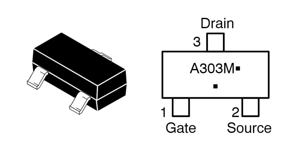
| ピン番号 | ピン名 | 説明 |
|---|---|---|
| 1 | G(ゲート) | MOSFET gate, control terminal |
| 2 | S(出典) | MOSFET source, typically connected to ground |
| 3 | D(ドレイン) | MOSFET drain, connected to the load |
When you’re hooking up this MOSFET, here are a few key tips. First, the gate (G) pin controls the MOSFET’s on and off states—keep its voltage within ±8V to prevent damage. It’s smart to add a small gate resistor, usually a few dozen ohms, to reduce noise and ringing.
Your source (S) pin should be connected directly to ground or your circuit’s common reference point, with short and wide connections to ensure solid grounding and better heat dissipation.
The drain (D) pin connects to your load. Always double-check that the load’s voltage and current don’t exceed the MOSFET’s limits (25V, 0.68A). Also, pay attention to proper heat management—give plenty of PCB area between the drain and source for good heat dissipation.
Lastly, always handle the device carefully to avoid static damage, and follow all recommended ratings in the datasheet to keep your setup safe and reliable.
Fdv303n Equivalent Mosfet Transistor

| パラメータ | FDV303N | FDV301N | FDN337N | IRLML6344 |
|---|---|---|---|---|
| パッケージ | SOT-23 | SOT-23 | SOT-23 | SOT-23 |
| 極性 | Nチャネル | Nチャネル | Nチャネル | Nチャネル |
| 最大ドレイン-ソース電圧(VDS) | 25V | 25V | 30V | 30V |
| Continuous Drain Current (ID) | 0.68A | 0.22A | 0.5A | 3.3A |
| On-Resistance RDS(オン) | 0.45Ω @ 4.5V | 1.2Ω @ 4.5V | 0.3Ω @ 4.5V | 0.045Ω @ 4.5V |
| ゲート閾値電圧(VGS(番目)) | 0.8V | 0.8V | 1.0V | 1.0V |
| Max Gate-Source Voltage (VGS) | ±8V | ±8V | ±20V | ±20V |
| Max Power Dissipation (PD) | 350mW | 225mW | 300mW | 1.25W |
| Input Capacitance (Ciss) | 50pF | 30pF | 60pF | 150pF |
| Total Gate Charge (Qグラム) | 2.3nC | 1.5nC | 2.0nC | 4.5nC |
| ESD保護 | Yes (>6kV) | はい | はい | はい |
| メーカー | オンセミ | オンセミ | オンセミ | インフィニオン |
If you’re thinking about swapping out the FDV303N MOSFET, here’s what you need to watch for. First, always match the key specs—check your new MOSFET’s voltage rating (V_DS), current rating (I_D), and on-resistance (R_DS(on)) carefully. For instance, IRLML6344 has lower resistance and can handle higher currents, making it a good pick if you need more power.
Also, make sure your replacement MOSFET has a similar gate threshold voltage (V_GS(th)) so it turns on reliably with your existing drive voltage. Thankfully, replacements typically come in the same SOT-23 package, so you won’t need to redesign your PCB.
Don’t overlook heat management—choose a MOSFET with suitable power dissipation to prevent overheating. Lastly, if static electricity could be an issue, pick one with solid ESD protection, like FDV303N (>6kV) or IRLML6344, to keep things safe.
Fdv303n Switching Circuit Schematic
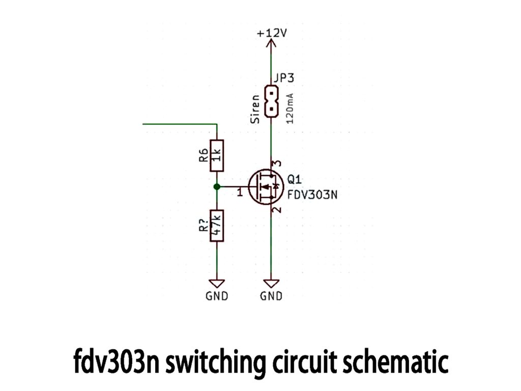
Here’s how your FDV303N MOSFET low-side switch works in a simple setup. You’re using it to control a 12V siren with just a small control signal like 3.3V or 5V. Connect the MOSFET gate (pin 1) through a 1kΩ resistor to your control signal to keep the gate stable and protected. Add a 47kΩ resistor to ground, so the MOSFET stays off when there’s no input signal, avoiding accidental triggers.
When your control signal goes high, the MOSFET gate voltage rises above its threshold (around 0.8-1V), switching the MOSFET on and activating your siren. When the signal drops to low, the MOSFET turns off, cutting the power to the siren.
Always ensure your gate voltage stays within ±8V. Although the MOSFET can handle more current (0.68A) and voltage (25V) than you need here, make sure your PCB layout includes proper heat dissipation, especially if your load is inductive—add a diode for extra protection.
Fdv303n Mosfet Gate Voltage
When you’re using the FDV303N MOSFET, it’s important to keep an eye on the gate voltage. Never let it exceed ±8V between the gate and source—going beyond this could permanently damage your MOSFET.
Typically, you’ll drive it with standard logic levels like 2.5V, 3.3V, or 5V. At voltages below 0.8V, your MOSFET stays off. Around 0.8V to 1V, it just starts turning on, but won’t handle much current yet. For reliable switching, stick to gate voltages of at least 2.5V.
Make sure to add a small resistor (usually a few tens to hundreds of ohms) in series with the gate to protect it from current spikes. Also, don’t leave the gate pin floating—connect a large resistor (like 47kΩ to 100kΩ) to ground to keep it stable and avoid accidental triggers.
Fdv303n Logic Ievel Mosfet Application
If you’re looking at using the FDV303N MOSFET, it’s a fantastic choice for logic-level circuits. It switches easily with low voltages around 3.3V or 5V, thanks to its low threshold voltage of about 0.8V. Plus, it has a low on-resistance (around 0.45Ω at 4.5V), making it efficient for handling loads like LEDs, relays, or motors.
Common uses include low-side switching, PWM-driven lighting or motor speed control, and even simple level shifting from low to higher voltages. Remember to always use a small resistor (around 100Ω) at the gate to protect it from voltage spikes and noise. Keep your gate voltage within the ±8V limit to avoid damage, and use a pulldown resistor to keep the gate from floating.
Also, ensure your PCB layout provides adequate heat dissipation, especially if you approach the MOSFET’s 0.68A current limit.
同様のもの
~~3.jpg "IRFU9024NPBF")
IRFU9024NPBF
インターナショナル・レクティファイアー

FDG6335N
オンセミ

MMBBFJ201
オンセミ

IRF3205PBF
インターナショナル・レクティファイアー

IRFP1405PBF
インターナショナル・レクティファイアー

IRF3205ZSTRLPBF
インターナショナル・レクティファイアー

IRFP4229PBF
インターナショナル・レクティファイアー

IRFB7437PBF
インターナショナル・レクティファイアー
.jpg "IRLR9343TRPBF")
IRLR9343TRPBF
インターナショナル・レクティファイアー
IRFP4468PBF
インターナショナル・レクティファイアー
IRF640NSTRLPBF
インターナショナル・レクティファイアー

FDS6375
ナショナルセミコンダクター
カートに追加する

IXTN210P10T
イクシス

IRLML0040TRPBF
インフィニオンテクノロジーズ

SIS434DN-T1-GE3
ビシェイ・シリコニクス
2N7002K-T1-E3
ビシェイ・シリコニクス

SUD50P06-15L-E3
ビシェイ・シリコニクス

FDMC8327L
オンセミ

BSS84
大うつ病性障害

IRLL3303TRPBF
インターナショナル・レクティファイアー

FDMC86259P
オンセミ

IRLHM620TRPBF
インフィニオンテクノロジーズ

STP4NK80ZFP
STマイクロエレクトロニクス

DMP6110SVT-7
ダイオード株式会社
関連製品
IRFU9024NPBF
インターナショナル・レクティファイアー
FDG6335N
オンセミ
MMBBFJ201
オンセミ
IRF3205PBF
インターナショナル・レクティファイアー
IRFP1405PBF
インターナショナル・レクティファイアー
IRF3205ZSTRLPBF
インターナショナル・レクティファイアー
IRFP4229PBF
インターナショナル・レクティファイアー
IRFB7437PBF
インターナショナル・レクティファイアー
IRLR9343TRPBF
インターナショナル・レクティファイアー
IRFP4468PBF
インターナショナル・レクティファイアー
IRF640NSTRLPBF
インターナショナル・レクティファイアー
FDS6375
ナショナルセミコンダクター
IRFB4332PBF
インターナショナル・レクティファイアー

IRFP3306PBF
インターナショナル・レクティファイアー

NVTFS5811NLTAG
オンセミ
NVTFS4823NTWG
オンセミ

NVD5117PLT4G
オンセミ
IRF200S234
インフィニオンテクノロジーズ
.jpg "IRF840PBF")
IRF840PBF
インフィニオンテクノロジーズ

AO4407
アルファ・アンド・オメガ・セミコンダクター株式会社

2SK3377-Z-E1-AZ
ルネサス エレクトロニクス アメリカ株式会社

NVD5867NLT4G
オンセミ

NVMFS5A160PLZWFT1G
オンセミ

FDWS9510L-F085
オンセミ
FDWS9509L-F085
オンセミ
NVTFS5826NLWFTAG
オンセミ

AON7401L
アルファ・アンド・オメガ・セミコンダクター株式会社
AO4407AL
アルファ・アンド・オメガ・セミコンダクター株式会社

AO3407
アルファ・アンド・オメガ・セミコンダクター株式会社

CPH3461-TL-W
オンセミ
RFQ をお送りください。すぐに対応させていただきます。
