
IR2113S 回路とデータシート | ピン配置
- 動作電源電圧: -
- REACH - SVHC: -
- 入力電圧 - 最小: -
- パッケージ: -


HK$250.00以上のご注文で送料無料

迅速な対応、迅速な見積もり

すぐに発送、アフターサービスも安心

オリジナルチャネル、本物の製品の保証
IR2113
IR2113S
If you’re designing a half-bridge or full-bridge circuit, IR2113S is an ideal driver. It drives both high-side and low-side N-channel MOSFETs at up to 600V on the high side, perfect for high-voltage applications. It offers ±2A peak output current for powerful MOSFETs, built-in dead-time to avoid shoot-through, and UVLO protection on both sides for stability. The inputs support 3.3V and 5V logic signals, and the compact SOP package helps simplify PCB layout.
IR2113S Pinout
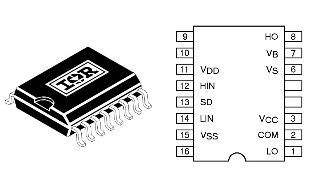
| ピン番号 | ピン名 | タイプ | 機能説明 |
|---|---|---|---|
| 1 | LO | 出力 | Low-side gate drive output, drives the lower MOSFET gate |
| 2 | コム | Power Ground | Low-side driver reference ground, usually connected to power ground |
| 3 | VCC | 力 | Logic power supply input (typically 10–20V), powers internal logic and low-side driver |
| 4 | VS | Floating Supply | High-side driver reference, connected to the source of the high-side MOSFET |
| 5 | VB | 力 | High-side driver supply, bootstrapped by external diode and capacitor |
| 6 | HO | 出力 | High-side gate drive output, drives the upper MOSFET gate |
| 7 | VSS | 信号グランド | Control logic ground (typically same as COM) |
| 8 | ノースカロライナ州 | 予約済み | No connection |
| 9 | ノースカロライナ州 | 予約済み | No connection |
| 10 | SD | 入力 | Shutdown input (low = disable HO/LO outputs) |
| 11 | ヒン | 入力 | High-side control signal input (high = HO output) |
| 12 | リン | 入力 | Low-side control signal input (high = LO output) |
| 13 | VSS | 信号グランド | Same as Pin 7 (may be connected internally) |
| 14 | VCC | 力 | Same as Pin 3 (may be connected internally) |
| 15 | コム | Power Ground | Same as Pin 2 |
| 16 | LO | 出力 | Same as Pin 1 |
When you’re wiring up the IR2113S, add a bootstrap capacitor (0.1~1μF) between VB and VS to power the high-side MOSFET properly. HIN/LIN inputs are logic-level compatible (TTL/CMOS)—never connect them directly to high voltage. The SD pin can shut off both MOSFETs if pulled low, perfect for protection. COM and VSS should share the same ground reference. Also, keep enough dead-time to prevent shoot-through. For higher voltages (300V or more), maintain proper spacing around VB/VS lines to avoid insulation issues or arcing.
IR2113S Equivalent


| パラメータ/モデル | IR2113S | IR2110S | IRS2186S | IRS21094S |
|---|---|---|---|---|
| High-side Drive Voltage Range | 10–600V | 10–600V | Max 80V | 10–200V |
| 電源電圧(Vcc) | 10–20V | 10–20V | 10–20V | 10–20V |
| Output Current Capability | 2A / 2A | 2A / 2A | 1.4A / 1.8A | 0.6A / 1.3A |
| Operating Frequency Support | High (>100kHz) | High (>100kHz) | Medium (~200kHz) | 中くらい |
| Dead Time Programmable | はい | はい | いいえ | いいえ |
| パッケージタイプ | SOIC-16 | SOIC-16 | SOIC-8 | SOIC-8 |
| Under-voltage Lockout Protection | はい | はい | はい | はい |
If you’re currently using the IR2113S and looking for an alternative, the IR2110S is your closest match—similar specs and package, just slightly different pin functions, so check the datasheet carefully. IRS2186S and IRS21094S come in smaller SOIC-8 packages with simpler features, better for compact, lower-voltage designs. Avoid these two for high-voltage applications like a 600V full-bridge. Always match your requirements in voltage rating, current capability, and package size before deciding.
IR2113S Half Bridge Driver Circuit
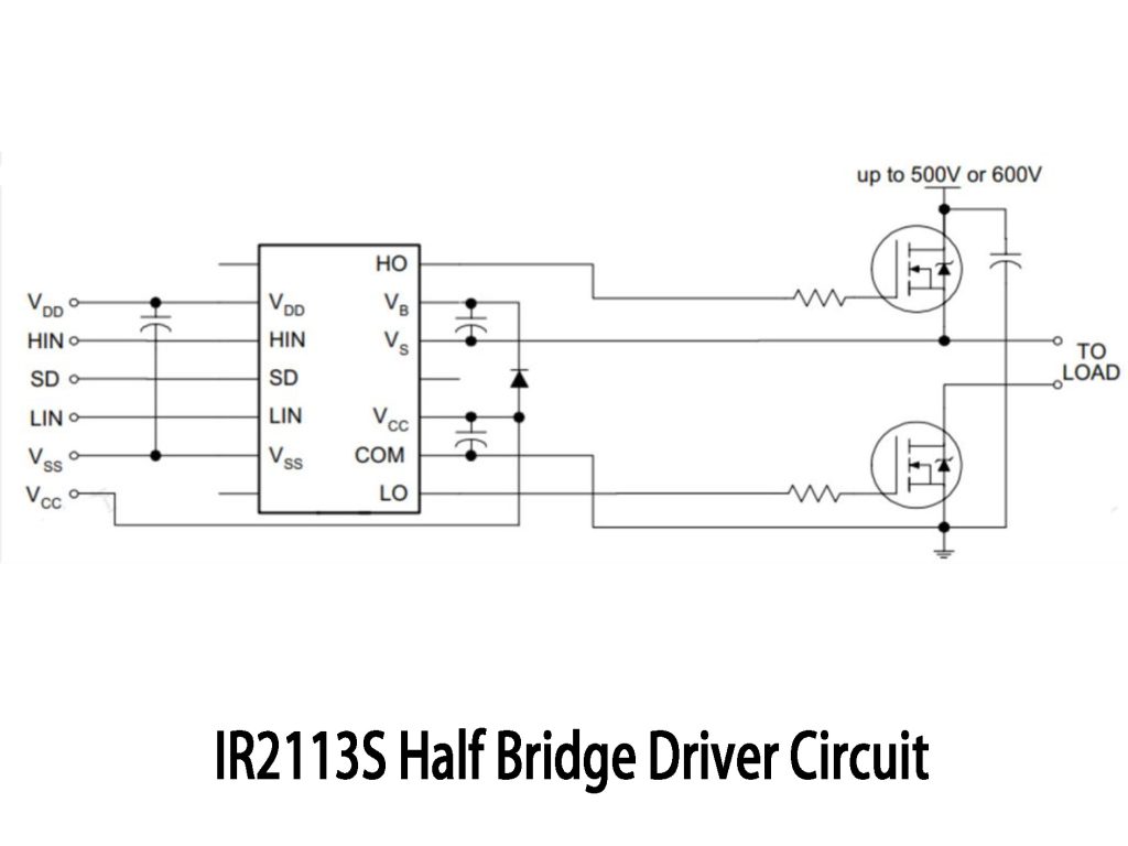
This circuit is a typical IR2113S half-bridge driver, common in motor control or high-voltage inverter applications. Your control signals (HIN/LIN) switch the MOSFETs through IR2113S, which manages dead-time protection internally. The bootstrap capacitor between VB and VS boosts voltage to drive the high-side MOSFET. It supports voltages up to 600V; logic supply is usually around 12V. Be careful with high-voltage spacing in your layout.
IR2113S MOSFET Driver Application
If you’re looking for a reliable half-bridge driver, IR2113S is a great pick, especially when driving high-voltage N-channel MOSFETs. It’s perfect for motor drives (like BLDC or servo motors), DC-AC inverters (solar, UPS), high-frequency switching power supplies, wireless charging, and induction heating. It’s also useful in variable-frequency drives for industrial fans or AC compressors. Overall, it fits many high-voltage applications.
IR2113S Inverter Control Schematic
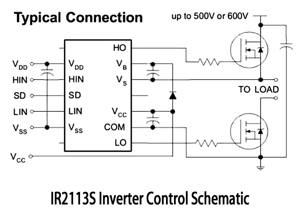
Check out this IR2113S inverter schematic—it’s essentially a half-bridge inverter. The IR2113S chip drives two N-channel MOSFETs (high-side and low-side) via HIN and LIN signals from your controller. The SD pin lets you safely disable the outputs. A bootstrap capacitor provides voltage for the high-side MOSFET. PWM signals alternate MOSFET switching, creating an AC output suitable for UPS, solar inverters, or motor drives. It easily handles high voltages around 500-600V DC, making it highly practical for various applications.
同様のもの

ZXCW6100S28
ダイオード株式会社

TDA8541T/N1,112
NXP USA Inc.

TDA8541T/N1,118
NXP USA Inc.

TDA7056B/N1,112
NXP USA Inc.
,SOT157-2.JPG "TDA2616Q/N1,112")
TDA2616Q/N1,112
NXP USA Inc.

TDA8547TS/N1,112
NXP USA Inc.
TDA8547TS/N1,118
NXP USA Inc.

NE58633BS,157
NXP USA Inc.
NE58633BS,115
NXP USA Inc.

SA58670BS,115
NXP USA Inc.

TS4961TIQT
STマイクロエレクトロニクス
,SOT523-1.JPG "TFA9842J/N1,112")
TFA9842J/N1,112
NXP USA Inc.
カートに追加する

LTC3765EMSE#TRPBF
アナログ・デバイセズ株式会社

VSP01M01ZWDR
テキサス・インスツルメンツ

LM385M3X-1.2
テキサス・インスツルメンツ

ISD4002-240ED
ヌヴォトンテクノロジー株式会社

LTC6994IDCB-2#TRMPBF
アナログ・デバイセズ株式会社

PIC16F1828T-I/SO
マイクロチップテクノロジー

LT3048IDC-15
アナログ・デバイセズ株式会社

TPS259541DSGT
テキサス・インスツルメンツ

TAS5122DCA
テキサス・インスツルメンツ

TSB43EB42ZGU
テキサス・インスツルメンツ

CY37512P256-83BGC
サイプレスセミコンダクタ社

SNJ54ALS191FK
テキサス・インスツルメンツ
関連製品
ZXCW6100S28
ダイオード株式会社
TDA8541T/N1,112
NXP USA Inc.
TDA8541T/N1,118
NXP USA Inc.
TDA7056B/N1,112
NXP USA Inc.
TDA2616Q/N1,112
NXP USA Inc.
TDA8547TS/N1,112
NXP USA Inc.
TDA8547TS/N1,118
NXP USA Inc.
NE58633BS,157
NXP USA Inc.
NE58633BS,115
NXP USA Inc.
SA58670BS,115
NXP USA Inc.
TS4961TIQT
STマイクロエレクトロニクス
TFA9842J/N1,112
NXP USA Inc.

SA58632BS,118
NXP USA Inc.

TDA1308TT/N2,118
NXP USA Inc.
TDA8552TS/N1,112
NXP USA Inc.
TDA8552TS/N1,118
NXP USA Inc.
TDA1517/N3,112
NXP USA Inc.
TDA7056A/N2,112
NXP USA Inc.

SA58671UK,027
NXP USA Inc.

TDA8948J/N1,112
NXP USA Inc.
TFA9843AJ/N1,112
NXP USA Inc.

SA58637BS,118
NXP USA Inc.

TDA7052A/N2,112
NXP USA Inc.

TDA8551T/N1,112
NXP USA Inc.

TDA8551T/N1,118
NXP USA Inc.
SA58672UK,027
NXP USA Inc.
SA58670ABS,115
NXP USA Inc.

SA58631TK,157
NXP USA Inc.
SA58631TK,118
NXP USA Inc.
SA58631TK,115
NXP USA Inc.
RFQ をお送りください。すぐに対応させていただきます。
