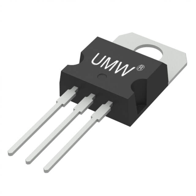
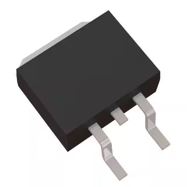
IRFB4110 データシート、同等品、コントローラー、ピン配置
- サプライヤーデバイスパッケージ: TO-220AB
- FETタイプ: Nチャネル
- ドレイン-ソース電圧(Vdss): 100V
- パッケージ: TO-220-3

HK$250.00以上のご注文で送料無料

迅速な対応、迅速な見積もり

すぐに発送、アフターサービスも安心

オリジナルチャネル、本物の製品の保証
IRFB4110 MOSFET Complete Details | Working Principle and Best 5 Equivalent MOSFETs
IRFB4110
The IRFB4110 is an N-channel MOSFET, perfect for high-current applications. With a drain-source voltage of 100V and a continuous drain current of 120A at 25°C, it’s built to handle serious power. The gate threshold voltage ranges from 2.0V to 4.0V, and with an Rds(on) of just 0.014Ω at 10V, it minimizes conduction losses, making it efficient for power-sensitive tasks. It can dissipate up to 150W of power, and its TO-220 package makes it easy to integrate into your designs. This MOSFET is a solid choice for applications like DC-DC converters, motor drivers, and other high-current power conversions, offering excellent performance with low losses for fast switching.
IRFB4110 MOSFET Pinout Diagram

| ピン | ピン名 | 説明 |
|---|---|---|
| 1 | ゲート(G) | Controls the MOSFET’s switching. A voltage applied here turns the MOSFET on. |
| 2 | ドレイン(D) | Connected to the load or the negative terminal of the power supply. This is where the current flows out. |
| 3 | 出典(S) | Connected to the ground or the negative side of the circuit, providing the path for current to flow back to the power supply. |
When using the IRFB4110 MOSFET, the Gate pin controls whether the MOSFET is on or off. To turn it on, you’ll need to apply a voltage (usually 10V) between the Gate and Source, allowing current to flow from the Drain to the Source. The Drain pin is where the current enters the MOSFET, typically connected to your load. When the MOSFET is on, the current flows from the Drain to the Source. The Source pin is where the current exits the MOSFET, usually connected to ground or the negative terminal of your circuit.
Keep an eye on the Gate voltage to make sure the MOSFET switches correctly. Also, if you’re using the IRFB4110 for high-power applications, be aware that it can get pretty hot when handling large currents, so you might need a heatsink to keep things cool and running safely.
IRFB4110 Equivalent MOSFET Transistor

| パラメータ | IRFB4110 | IRLB3034 | STP75NF75 | FDPF9N50 | IRF540N |
|---|---|---|---|---|---|
| Vds (V) | 100 | 55 | 75 | 50 | 100 |
| Id (A) | 120 | 120 | 80 | 90 | 33 |
| Rds(on) (Ω) | 0.014 | 0.004 | 0.010 | 0.020 | 0.077 |
| Vgs(th) (V) | 2.0 – 4.0 | 1.0 – 3.0 | 1.0 – 2.5 | 2.0 – 4.0 | 2.0 – 4.0 |
| P(max) (W) | 150 | 150 | 150 | 150 | 150 |
| パッケージ | TO-220 | TO-220 | TO-220 | TO-220 | TO-220 |
| Gate Charge (nC) | 120 | 150 | 140 | 120 | 120 |
If you’re looking for alternatives to the IRFB4110, here are a few options. The IRLB3034 has a lower Rds(on), which makes it more efficient for high-current applications, but it’s rated for 55V, so it might not be suitable for circuits needing 100V. The STP75NF75 also has a lower Rds(on), which means less power loss, but it can handle only 80A, which is lower than the IRFB4110’s 120A. The FDPF9N50 is a good fit if voltage isn’t a big issue, with an Rds(on) of 0.020Ω, but its Vds is just 50V. The IRF540N is closer to the IRFB4110 in Vds, but with a higher Rds(on), so it will generate more heat at the same current and is better suited for lower-power applications.
When choosing a replacement, consider the Vds, Rds(on), and current ratings. Make sure the MOSFET meets or exceeds these specs, and keep an eye on the Gate Charge (Qg) to avoid slow switching speeds.
IRFB4110 Switching Circuit Schematic

In this switching test circuit, the IRFB4110 MOSFET is the device under test (DUT). The circuit uses a voltage source (V_DS) to apply source-drain voltage to the MOSFET and controls its switching using a high-frequency pulse signal at the gate (V_GS). The pulse is very short (less than 1 microsecond) with a low duty cycle (less than 0.1%), making the MOSFET switch on and off quickly. The circuit also includes an inductive load (L_D) to test how the MOSFET responds to voltage spikes when switching under inductive conditions. The main goal of this test is to measure the switching performance of the MOSFET, including its switching speed, turn-on time, and turn-off time. For the IRFB4110, this is especially important, as you want to make sure the MOSFET handles fast switching without excessive losses or voltage spikes.
IRFB4110 Inverter Power Stage Circuit

In this IRFB4110 inverter power stage circuit, the IRFB4110 MOSFET is the key switch that controls the current flow. The circuit gets its power from the VCC supply, which powers the MOSFET and the inductor. The inductor (L) acts as a load and stores energy during the switching process, simulating how motors or other inductive loads behave in an inverter. A 1K resistor helps manage the gate drive signal to ensure the MOSFET switches properly. A diode protects the circuit by providing a path for the reverse current when the MOSFET turns off, preventing damage from voltage spikes caused by the inductor. The circuit is similar to the power stage of an inverter, where the MOSFET switches DC power to produce AC output, controlling the current and voltage of the load. The inductor simulates the load characteristics, testing how the MOSFET handles switching and reverse current.
IRFB4110 Gate Driver Circuit Example

In this IRFB4110 gate driver circuit, the MOSFET is switched on and off by a gate driver, which makes sure it switches quickly and reliably. The gate driver takes a pulse-width modulation (PWM) signal and adjusts the gate-source voltage (V_GS) to control the MOSFET’s switching. The driver boosts the voltage to about 15V, which is enough to efficiently drive the MOSFET. The inductor (L) acts as the load the MOSFET controls, while the resistor (R_G) limits the current into the gate to protect the MOSFET. When the MOSFET is switched on, it allows current to flow; when switched off, it blocks the current. This circuit is mainly used to test how well the IRFB4110 handles fast switching and whether it can effectively control the load without overheating or failing.
IRFB4110 High Current DC Motor Driver
When you’re working with a DC motor driver circuit, you want to make sure the components are up to the task. The IRFB4110 MOSFET is key here—it handles high current loads easily, making it perfect for controlling the motor. The H-Bridge setup lets you control the motor’s direction, and by turning on different pairs of MOSFETs, you can switch between forward and reverse rotation. For speed control, you’ll use PWM (Pulse Width Modulation). This lets you adjust the motor’s speed by tweaking the duty cycle, which affects how much power the motor gets. The current sense resistor keeps an eye on the current and protects the motor and MOSFETs if things get too intense. Freewheeling diodes are there to save the day by preventing voltage spikes when switching off the MOSFETs, protecting your setup. And with a gate driver IC, the MOSFETs turn on and off smoothly, making everything run efficiently.
