
IRFB4227 データシート、アンプ、価格、PDF
- トランジスタタイプ: 1 Nチャネル
- 標準的なターンオフ遅延時間: 21ナノ秒
- 標準的なターンオン遅延時間: 33ナノ秒
- パッケージ: -


HK$250.00以上のご注文で送料無料

迅速な対応、迅速な見積もり

すぐに発送、アフターサービスも安心

オリジナルチャネル、本物の製品の保証
1KW IRS2092 + IRFB4227 Class D Mono Amp Unboxing (No Commentary)
irfb4227
If you’re looking for a powerful MOSFET for your high-voltage projects, the IRFB4227 is a great choice. It easily handles voltages up to 200V and currents up to 130A, making it ideal for heavy-duty applications. One of the best things about this transistor is its incredibly low on-resistance—just around 19.7 mΩ—so you’ll lose very little energy as heat, improving your circuit’s efficiency.
It’s also known for fast switching speeds and low gate charge, which means your system can handle high-frequency operations without demanding too much gate-drive current. Plus, its high avalanche energy rating helps protect your setup from sudden voltage spikes.
You’ll find this MOSFET especially useful in switch-mode power supplies, DC-DC converters, powerful inverters, motor drivers, and high-current amplifier circuits. With a convenient TO-220 package, it’s easy to mount and provides excellent heat dissipation, keeping your projects reliable and stable.
irfb4227 pinout and connection

| ピン番号 | ピン名 | 説明 |
|---|---|---|
| 1 | ゲート(G) | Gate, controls the MOSFET switching state. |
| 2 | ドレイン(D) | Drain, connects to the high-voltage end of the load. |
| 3 | 出典(S) | Source, typically connected to ground or the low-voltage end of the load. |
When wiring up your IRFB4227 MOSFET, keep these practical tips in mind to ensure reliability. The gate pin (G) is where you’ll apply your drive signal—typically around 10-15 volts—to switch the MOSFET on or off. Be careful not to exceed ±20V on this pin; otherwise, you risk damaging the MOSFET. A proper gate driver circuit is always recommended.
Your drain pin (D) connects directly to your load’s high-voltage side, like the positive power supply, relay coil, or motor driver circuit. Always check you’re not exceeding its maximum voltage (200V) or current rating (130A).
The source pin (S) usually goes straight to ground or the low-voltage side of your load, completing the circuit.
MOSFETs are sensitive to static electricity, so handle them carefully with anti-static precautions. Also, ensure adequate cooling—use a suitable heatsink to prevent overheating during heavy loads. Keep your gate wire short to avoid noise and interference. Lastly, if you’re controlling inductive loads like motors, add a diode to protect your MOSFET from voltage spikes.
irfb4227 equivalent mosfet transistor
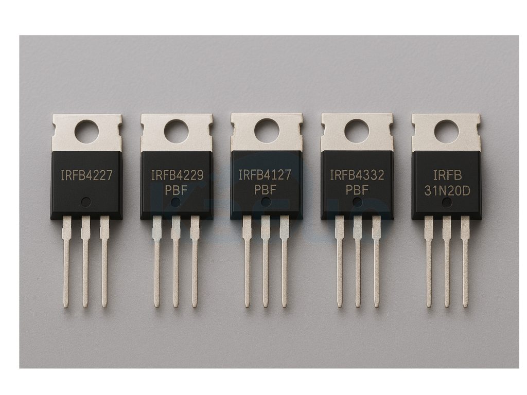
| パラメータ | IRFB4227 | IRFB4229PBF | IRFB4127PBF | IRFB4332PBF | IRFB31N20D |
|---|---|---|---|---|---|
| パッケージタイプ | TO-220 | TO-220AB | TO-220AB | TO-220AB | TO-220AB |
| Drain-Source Voltage (V_DS) | 200V | 250V | 200V | 150V | 200V |
| Drain Current (I_D) | 65 A | 46 A | 76 A | 60 A | 31 A |
| R_DS(オン) | 19.7 mΩ | 45 mΩ | 22 mΩ | 9.5 mΩ | 120 mΩ |
| Power Dissipation (P_D) | 330 W | 300 W | 300 W | 300 W | 150ワット |
| 主な特徴 | Prototype, suitable for high-power and high-voltage applications | Higher voltage applications | Higher current capability | Ultra-low R_DS(on), high efficiency | Medium power applications, relatively higher R_DS(on) |
When you’re considering swapping your IRFB4227 MOSFET for a different model, there are a few important points you’ll want to keep in mind. First, always double-check the replacement MOSFET’s voltage (V_DS) and current (I_D) ratings to ensure they can handle your circuit’s requirements safely.
A lower R_DS(on), like you’d find on the IRFB4332PBF, can boost efficiency by reducing losses, but remember that it might also affect how much heat your circuit produces—so factor this into your cooling design.
Even if both MOSFETs use the common TO-220 package, confirm the pin layout matches exactly to avoid unexpected issues during installation. Finally, each MOSFET handles power differently, so always read through the datasheet carefully and adjust your heat dissipation plan accordingly. Taking these steps helps ensure your circuit stays stable and reliable after switching components.
irfb4227 inverter circuit schematic & irfb4227 h-bridge design example
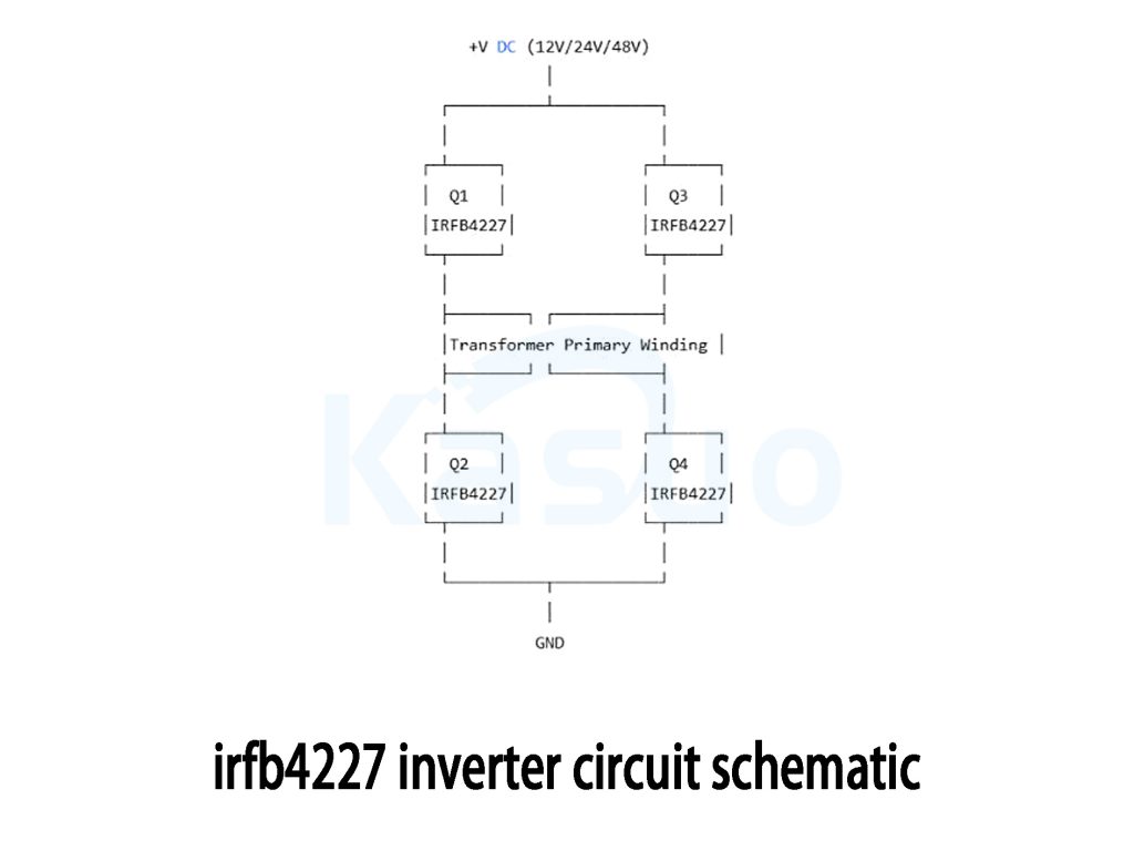
If you’re thinking about building an inverter to convert DC voltage (like 12V, 24V, or 48V) into AC, using IRFB4227 MOSFETs in an H-bridge setup is a smart choice. Basically, you’ll set up four MOSFETs (Q1-Q4) to form an H-bridge circuit. By switching pairs of these MOSFETs alternately, you push current back and forth through a transformer’s primary winding, generating AC power on the secondary side.
Use dedicated gate-driver chips, like the IR2110 or IR2104, to ensure your MOSFET gates get the proper drive voltage (around 10-15V). Remember to include a small delay (dead-time) in your PWM signals to prevent short-circuits.
Don’t forget protection diodes to handle voltage spikes, and always provide enough cooling for your MOSFETs—they can get hot under high loads. Keep your high-current PCB traces thick and your gate wiring short. This type of inverter is ideal for off-grid solar setups, vehicle power converters, UPS systems, or industrial motor drivers, and you can expect efficiencies around 90% or better with good design practices.
irfb4227 mosfet gate driver circuit

When you’re working with high-power MOSFETs like the IRFB4227, it’s essential to use a proper gate-driver circuit to switch them efficiently. Think of the PWM controller as your signal generator—it outputs pulses that tell the MOSFET when to turn on and off. But the MOSFET’s gate acts like a capacitor, needing a strong push-pull amplifier (made of complementary transistors) to quickly charge and discharge it, ensuring rapid switching and better efficiency.
You’ll need resistors to protect the transistors and control current, plus a gate resistor to prevent ringing and interference. Keep your PCB traces short and thick to reduce parasitic effects. Choose a gate resistor carefully (usually a few ohms) to balance EMI and switching speed.
Use a stable 12-15V gate-drive voltage to ensure reliable operation. You’ll commonly see this setup in power inverters, motor controllers, and switching power supplies—anywhere you need fast, efficient, and reliable MOSFET operation.
irfb4227 high current switching application
If you’re planning to build a powerful DC switching or inverter project, the IRFB4227 MOSFET is your best friend. It can easily handle very high currents—up to 65A continuously and even higher peaks—thanks to its ultra-low on-resistance of just about 19.7 mΩ. This makes it perfect for DC load switches, motor controllers, big DC-to-AC inverters, battery protection circuits, and DC-DC converters.
For smooth switching, you’ll want a solid gate driver like the IR2110 or TC4420 to provide a stable 12-15V gate signal. Always make sure your PCB layout includes thick, short connections to handle these high currents safely and efficiently.
Since high current generates plenty of heat, use a good heat sink or even cooling fans to keep your MOSFET cool. Adding protective diodes will safeguard it from voltage spikes, especially if you’re controlling inductive loads like motors. Done right, you’ll achieve excellent efficiency, typically over 90%, making your setup reliable and powerful for applications like electric vehicles, solar power systems, and heavy-duty tools.
同様のもの

RBQ20NS65AFHTL
ロームセミコンダクター

V20D100C-M3/I
Vishay General Semiconductor - ダイオード部門
V20D60C-M3/I
Vishay General Semiconductor - ダイオード部門

BYV32E-200PQ
ウィーエン・セミコンダクターズ
VT2060C-E3/4W
Vishay General Semiconductor - ダイオード部門

30CTQ050-1
SMCダイオードソリューション

30CTQ045-1
SMCダイオードソリューション

30CTQ040-1
SMCダイオードソリューション

SR2060
台湾セミコンダクター株式会社
SR2040
台湾セミコンダクター株式会社
MBR2060CT
台湾セミコンダクター株式会社
GP1606
台湾セミコンダクター株式会社
カートに追加する
F417MR12W1M1HB76BPSA1
インフィニオンテクノロジーズ

BCR2PM-14LE#B00
ルネサス エレクトロニクス アメリカ株式会社

DDTC124GCA-7-F
ダイオード株式会社
,TO-226_straightlead.jpg "FJN3307RBU")
FJN3307RBU
オンセミ

MA26V2200A
パナソニック電子部品

ETZ1100N16P70HPSA1
インフィニオンテクノロジーズ
NCG100F475NF120
オンセミ

MCH3414-EBM-TL-E
オンセミ

L0109MTRP4
リテルヒューズ株式会社
.jpg "S6008RS3TP")
S6008RS3TP
リテルヒューズ株式会社

BZB784-C11,115
ネクスペリアUSA株式会社

IRG4BC30W-S
インフィニオンテクノロジーズ
関連製品
RBQ20NS65AFHTL
ロームセミコンダクター
V20D100C-M3/I
Vishay General Semiconductor - ダイオード部門
V20D60C-M3/I
Vishay General Semiconductor - ダイオード部門
BYV32E-200PQ
ウィーエン・セミコンダクターズ
VT2060C-E3/4W
Vishay General Semiconductor - ダイオード部門
30CTQ050-1
SMCダイオードソリューション
30CTQ045-1
SMCダイオードソリューション
30CTQ040-1
SMCダイオードソリューション
SR2060
台湾セミコンダクター株式会社
SR2040
台湾セミコンダクター株式会社
MBR2060CT
台湾セミコンダクター株式会社
GP1606
台湾セミコンダクター株式会社

MBRS1045CTH
台湾セミコンダクター株式会社
16CTQ150
SMCダイオードソリューション

V10D45CHM3_A/I
Vishay General Semiconductor - ダイオード部門
NRVHP8H200MFDWFT3G
オンセミ

VBT1545CBP-E3/4W
Vishay General Semiconductor - ダイオード部門
VBT1545CBP-E3/8W
Vishay General Semiconductor - ダイオード部門
MBR2080CT-G
コムチップテクノロジー
MBR2060CT-G
コムチップテクノロジー
MBR2050CT-G
コムチップテクノロジー
MBR2040CT-G
コムチップテクノロジー
MBR2030CT-G
コムチップテクノロジー
UGB10DCT-E3/45
Vishay General Semiconductor - ダイオード部門
UGB10CCT-E3/45
Vishay General Semiconductor - ダイオード部門
UGB10BCT-E3/45
Vishay General Semiconductor - ダイオード部門

SDUR3020CT
SMCダイオードソリューション

RBQ15BM45AFHTL
ロームセミコンダクター

SDUR3040CT
SMCダイオードソリューション

V10K170C-M3/H
Vishay General Semiconductor - ダイオード部門
RFQ をお送りください。すぐに対応させていただきます。
