LM311N datasheet & comparator circuit | pinout, pdf Texas Instruments
- Type: General Purpose
- Number of Elements: 1
- Output Type: DTL, MOS, Open-Collector, Open-Emitter, RTL, TTL
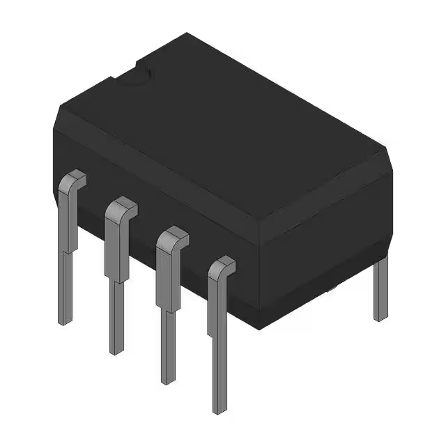
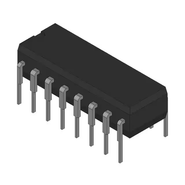
- Package: 8-DIP (0.300, 7.62mm)

FREE delivery for orders over HK$250.00

Quick response, quick quotaton

Flash shipment,no worries after sales

Original channel,guarantee of the authentic products
Key Features of the LM311N Comparator
The LM311N is a versatile, high-speed comparator that’s perfect for signal comparison in various applications. It features a wide input voltage range, from 3V to 40V, and operates with a single or dual power supply. With its open collector output, the LM311N can easily interface with other components, making it suitable for both digital and analog circuits. It’s commonly used in pulse-width modulation, voltage level detection, and zero-crossing detection circuits. The LM311N offers fast response times and reliable performance, making it a go-to choice for low-voltage systems and precision signal processing.
LM311N Pinout
| Pin | Label | Description |
|---|---|---|
| 1 | Offset Null | Used to adjust the offset voltage to minimize any input offset. |
| 2 | Inverting Input | The negative input for the comparator (signal input). |
| 3 | Non-Inverting Input | The positive input for the comparator (signal input). |
| 4 | V- | Negative power supply pin, connected to the system ground or negative voltage. |
| 5 | Output | Open collector output for the comparator’s result. |
| 6 | V+ | Positive power supply pin. |
| 7 | Offset Null | Used to adjust the offset voltage for the second comparator section. |
Using the LM311N Pinout
To use the LM311N comparator, connect your input signals to the Inverting Input (Pin 2) and Non-Inverting Input (Pin 3) based on your circuit’s logic. The V+ (Pin 6) and V- (Pin 4) pins should be connected to your power supply (typically a dual voltage supply). The Output (Pin 5) will provide the comparator result, which can be used for further processing. If needed, use the Offset Null pins (Pins 1 and 7) to adjust any offset voltage for precise operation. Make sure the power supply voltage is within the specified range to avoid damage and ensure proper functioning.
LM311N Equivalent Models
Here’s a comparison of equivalent comparators with similar packaging and performance:
| Model | Voltage Range | Output Type | Response Time | Package Type | Input Voltage Range |
|---|---|---|---|---|---|
| LM311N | 3V to 40V | Open Collector | 0.3µs | DIP-8 | 0V to 40V |
| LM393 | 2V to 36V | Open Collector | 1µs | DIP-8 | 0V to 36V |
| TLV3201 | 1.8V to 5.5V | Open Collector | 1µs | SOIC-8 | 0V to 5.5V |
| LM339 | 2V to 36V | Open Collector | 1µs | DIP-14 | 0V to 36V |
Substitution Tips
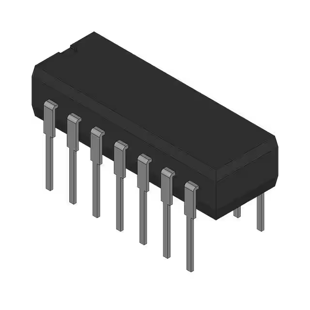
When replacing the LM311N, make sure the voltage range and output type are compatible with your circuit. For instance, the LM393 and LM339 are both open collector comparators with similar features, but the LM339 comes in a larger DIP-14 package. The TLV3201 offers a smaller package size and works in lower voltage systems (1.8V to 5.5V), which is ideal for battery-powered designs. Always verify that the response time and input voltage range align with your specific application needs.
Is the LM311N an SCR?
No, the LM311N is not a Silicon Controlled Rectifier (SCR). It is a comparator, which is an analog device used to compare two input voltages and output a signal based on which input is higher. In contrast, an SCR is a type of semiconductor used for controlling power, typically in switching applications. While both are used in electronic circuits, they serve very different purposes. The LM311N is primarily used for signal comparison, while an SCR is used for controlling larger currents in power electronics.
LM311N Comparator Circuit Overview
The LM311N is a high-speed voltage comparator widely used in electronic circuits to compare analog signals. It operates over a wide voltage range and is compatible with TTL and MOS logic circuits. The output can drive lamps or relays, switching voltages up to 50V at currents as high as 50mA.
Circuit Diagram
Circuit Analysis
-
Power Supply: The LM311N can operate with a single supply voltage ranging from 5V to 30V or a dual supply of ±2.5V to ±15V.
-
Inputs: The comparator has two inputs: the non-inverting input (pin 2) and the inverting input (pin 3). The voltage difference between these inputs determines the output state.
-
Output: The output (pin 7) is an open-collector type, meaning it requires an external pull-up resistor to function correctly.
-
Strobe Function: The strobe pin (pin 6) can be used to disable the output, allowing for controlled timing in applications.
Important Considerations
-
Offset Adjustment: The LM311N includes offset adjustment pins (pins 1 and 5) to fine-tune the input offset voltage, ensuring accurate comparisons.
-
Output Drive Capability: While the LM311N can drive loads up to 50V and 50mA, it’s essential to ensure that the connected load does not exceed these limits to prevent damage.
-
PCB Layout: Proper PCB layout is crucial to minimize noise and ensure stable operation. Keep input and output traces short and separate to prevent feedback and oscillations.
This simple and efficient circuit is ideal for powering low-current devices like microcontrollers, sensors, and small LEDs.
