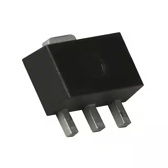
NESG2021M16-T3-A データシート、価格 | pdf
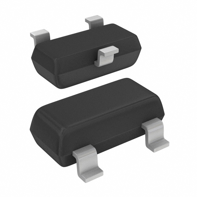
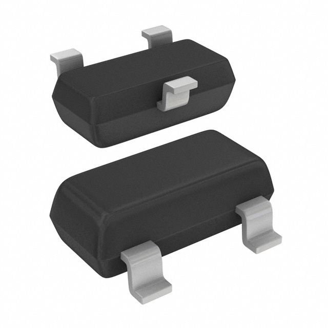
- パワーマックス: 175mW
- DCCurrentGain(hFE)(Min)@IcVce: 130 @ 5mA, 2V
- 電流コレクター(Ic)(最大): 35mA
- パッケージ: バルク

HK$250.00以上のご注文で送料無料

迅速な対応、迅速な見積もり

すぐに発送、アフターサービスも安心

オリジナルチャネル、本物の製品の保証
The NES model is known for its impressive versatility and solid performance, especially when it comes to gaming and entertainment systems. Originally developed for video game consoles, it’s recognized for delivering high-quality, reliable gameplay that has stood the test of time.
One of the key features of the NES model is its ease of use. It’s simple to set up, making it an ideal choice for both beginners and seasoned gamers. The console provides a wide range of classic games, offering a nostalgic experience for those who enjoyed the earlier days of gaming. Even though it’s a bit older, the NES still holds up due to its strong catalog of iconic titles.
Another reason the NES stands out is its robust design. While not as advanced as modern systems, its construction ensures durability and longevity. This makes it a great investment for collectors or anyone looking to relive the golden age of gaming.
Whether you’re looking to rediscover old favorites or experience the nostalgia of early gaming systems, the NES offers a reliable and enjoyable gaming experience. It’s a classic that continues to be loved by many.
Here’s the pinout for the NES controller connector:
| ピン番号 | ピン名 | 説明 |
|---|---|---|
| 1 | +5V | Power supply for the controller |
| 2 | クロック | Used to send data to the NES console |
| 3 | ラッチ | Latches the data from the controller |
| 4 | Data | Carries the button press data |
| 5 | 地面 | Common ground connection for the controller |
Usage and Considerations:
When connecting an NES controller to the console, ensure the wiring aligns properly with the pinout. The +5V pin must be connected to the power supply, and the ground pin should be attached to the common ground of the system. The clock and latch pins are important for syncing data transfer between the controller and the console, while the data pin carries the actual button input signals.
Make sure the cables and pins are not damaged, as loose or incorrect connections can cause the controller to malfunction or fail to register button presses. Also, handle the pins gently to avoid bending or breaking them, especially if you’re dealing with older hardware. Always double-check the connections before powering up the system to avoid any issues.
Here’s a comparison of alternative models that come in the same package as the NES controller connector, with important parameters listed for easy comparison:
| モデル | 電圧 | 現在 | Connector Type | 互換性 | 特徴 |
|---|---|---|---|---|---|
| ファミコン | 5V | 低い | 7-pin | NES consoles | Classic gaming, reliable input |
| SNES | 5V | 低い | 7-pin | SNES consoles | Compatible with SNES games |
| N64 | 3.3V | 適度 | 7-pin | N64 consoles | Analog input, advanced controls |
| Genesis | 5V | 低い | 9-pin | Sega Genesis | Multi-button input, simple layout |
Substitution Notes:
When switching between these controllers, it’s essential to ensure the voltage and connector type match. While the NES and SNES use the same 7-pin connector and 5V supply, the N64 controller works at a lower voltage (3.3V) and supports analog inputs, making it incompatible with NES or SNES systems. The Genesis controller, although also 5V and featuring a 9-pin connector, can’t be directly swapped with NES controllers without additional adapters.
If you plan to swap controllers across systems, always double-check both the connector and voltage requirements. Compatibility issues could prevent proper functionality or even damage your hardware, so it’s best to use controllers that are specifically designed for your console.
The NES controller operates using a straightforward yet clever design that efficiently transmits button inputs to the console. At its core, it employs a CD4021B 8-bit serial shift register, a component that converts the physical button presses into a serial data stream.
🧩 NES Controller Circuit Overview
Each of the NES controller’s eight buttons (A, B, Start, Select, Up, Down, Left, Right) is connected to an input pin on the shift register. When a button is pressed, it pulls its corresponding pin to ground (0V), indicating a logical ‘0’. If a button isn’t pressed, the pin is pulled up to 5V using a pull-up resistor, indicating a logical ‘1’ .
The shift register is clocked by the console via the ‘Clock’ line. Each clock pulse shifts the data bit through the register. The ‘Latch’ line is used to prepare the data for reading; when activated, it captures the current state of the shift register. The console then reads the data serially from the ‘Data’ line, interpreting the sequence of bits to determine which buttons are pressed.
⚙️ Practical Considerations
Understanding this circuit is particularly useful when interfacing NES controllers with modern systems, such as using an Arduino to emulate keyboard inputs. By replicating the shift register’s behavior, you can map the NES controller’s buttons to keyboard keys, allowing you to use the original controller with emulators or other applications.
However, it’s essential to note that the NES controller’s design is specific to its original hardware. While the shift register approach is efficient, it may not be directly compatible with all modern systems without additional interfacing circuitry. Therefore, when planning such integrations, ensure that the voltage levels and communication protocols are compatible to avoid potential damage to components.
In summary, the NES controller’s use of a shift register for serial data transmission is a testament to the ingenuity of early video game hardware design. This approach not only simplified the controller’s construction but also laid the groundwork for future developments in gaming peripherals.


SOT223-1.jpg)





.jpg)
,TO-226_bentlead.jpg)


